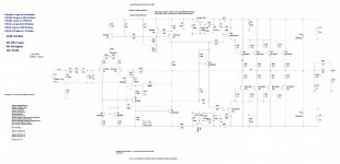
I am trying to simulate an 200W amp in Ltspice and measure its THD but do not know how to proceed.
Thanks to dadod for the input from his thread. The attached asc file is using his directives and the models files are from his post. I added the missing models to the Cordell-Models file.
The input section was copied from the SC200 https://www.diyaudio.com/forums/chi...ordell-super-gainclone-sc200-post5731705.html and the output of the circuit was copied from an amp by dadod. https://www.diyaudio.com/forums/solid-state/253039-unique-cfa-120-230w-amp-post3858433.html
Can anyone provide any easy to understand insight? I have tried Google and YouTube but nothing really straightforward.
There are also various errors flagged "Node N031 is floating", which I cannot understand as the connections appear complete to me.
Attachments
Check Sandro's videos on how to simulate (and much more). You can download the models he uses from his thread here on the forum, links are in the comments for the video's.
SW Audio - YouTube
SW Audio - YouTube
The input section was copied from the SC200 and the output of the circuit was copied from an amp by dadod.
Sorry to say, but output is not copied from Unique amp, where I used output triple.
Hi Damir. My bad. I guess it must have been from 200W/8ohm CFA. Unique CFA 120/230W amp in post #39. This one does have 4 each side on the output unless I'm mistaken (happens a lot).
Check Sandro's videos on how to simulate (and much more). You can download the models he uses from his thread here on the forum, links are in the comments for the video's.
SW Audio - YouTube
Thank you so much Rallyfinnen. I will check Sandro's videos .
There is no connection dot between r2 and c16 the input cap. Nor between c16 & c1. also on the input if I read the # wrong. Why have 2 input caps in series anyway?
Hi indianajo. I think you mean R2 and C19 and C19 and C1. I believe there would only be a 'dot' junction with three or more components. I have 'Mark Unconn Pins' selected in the 'View' menu and no unconnected pins are highlighted. I believe LTspice doesn't like the back to back caps. When I remove one, the error disappears.
The reason for having two back to back caps comes from the SC200 design.
Quote from Silicon Chip magazine "The signal passes through an RF attenuating RC low-pass filter (100 Ohm/1nF plus ferrite bead) and is coupled to the base of PNP transistor Q1 via a pair of series connected 47μF 25V electrolytic capacitors ( which are together more compact and cost less than an equivalent non-polarised capacitor)." I don't have the ferrite bead in my circuit.
There is no connection dot between R130 & C100, the zobel on the output. The R & C right before the output inductor.
I believe you are wrong, the components are connected; again, unless I'm missing something obvious, there would only be a 'dot' junction with three or more components. I checked the connections in LTspice on multiple occasions and they appear good.
Last edited:
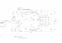
Hi Damir. My bad. I guess it must have been from 200W/8ohm CFA. Unique CFA 120/230W amp in post #39. This one does have 4 each side on the output unless I'm mistaken (happens a lot).
No, Unique use triple OPS, means predrivers, drivers and output transistors, your amp use just drivers and output bipolar transistors. In 200W CFA output transistors are mosfets.
No, Unique use triple OPS, means predrivers, drivers and output transistors, your amp use just drivers and output bipolar transistors. In 200W CFA output transistors are mosfets.
Hi Damir. Sorry, I'm confused. The amp I meant was the one I have attached below, which I downloaded from your post #39 which has 4 MJL4281C and 4 MJL4302C Complementary NPN-PNP Silicon Power Bipolar Transistors.
Attachments
Check Sandro's videos on how to simulate (and much more). You can download the models he uses from his thread here on the forum, links are in the comments for the video's.
SW Audio - YouTube
Hi Rallyfinnen,
Thanks for the great video recommendations. I watched the THD one's and managed to copy down the spice directives and add them to my schematic
")
There's a lot to learn but very well explained tutorials.
Emitter to emitter of drivers needs a resistor.
Thank you.
Could you recommend values and wattage please?
Follow as example this circuit
https://www.diyaudio.com/forums/att...lds-weirdest-dynaco-qsa-300-a-dyna300_pcb-png
https://www.diyaudio.com/forums/att...lds-weirdest-dynaco-qsa-300-a-dyna300_pcb-png
Thanks kokoriantz,
I used similar the values from the Honey Badger schematic and added the Cap. diyAB Amp The "Honey Badger" build thread. Would that work?
Any other suggestions are most welcome.
I used similar the values from the Honey Badger schematic and added the Cap. diyAB Amp The "Honey Badger" build thread. Would that work?
Any other suggestions are most welcome.
Attachments
- Status
- This old topic is closed. If you want to reopen this topic, contact a moderator using the "Report Post" button.
- Home
- Amplifiers
- Solid State
- 200W Amp Simulation Advice