Hi I must say a big thanks to everyone all the replies have been really helpful . I'm much more au fait with valve technology having repaired and modded mainly guitar and bass kit for over 40 years and had 2 years of tutorials from a ex senior Marshall designer, never really got into these ew fangled sid state stuff except for relatively simple pedals and amp stuff! Stereo stuff is way more complicated and without a circuit diagram I'm fighting a loosing battle. Brief recap as I might have one more go, right channel very distorted, full vbe multiplier supply of 1.1v on base of bd139, 30mv on output transistors left channel 1.1v supply with vtage drop to 5.9v on base of bd139 and around 10mv on emitters of output transistors .Assumed open base on left hand bd139 replaced it in correct orientation now had 0.88v instead of 1.1v and still full supply voltage of .88v on bd139 base checked both associated transistors which both have 32v on collector but only 0.4v on bases and 0.88v on emitters, right channel was still OK with 0.6v on bases and 1.1v on emitters. Double checking readings is when I shorted q313 both channel supply rail fuses blew q313 and both left hand channel output transistors
Blew. As I hadn't sorted vbe multiplier issues and couldn't find any other problems I'm not
convinced its worth pursuing any
Further without a circuit diagram although I don't like been defeated and I've only ly failed once to repair a bass amp with loads of smd in it, vile stuff especially when manufacturers refusing g to supply diagrams and parts anyway thanks again will let you know what I end up doing if not proceeding the amp or parts will free to a good home for postage cost
Don't give up so easily, take a photo of the circuit board and post the image. It should not be too hard for members to work out the general structure and get a handle on problems.
A transistor with a base emitter voltage of 0.6 Volts should be OK. Don't use your probes to measure between these connections - this practice is too risky as you have experienced.
Instead put the black probe into the speaker black output terminal and use the red probe to touch the emitter first and the base second and subtract the difference from the higher reading noting whether plus or minus.
To be systematic write the transistor Q number and the readings for each. A spreadsheet would be a useful way to record the detail and allow alterations to be made with progress in tracking faults. Usually circuit diagrams have some voltage readings shown at various points.
To avoid short circuits you could use a length of insulation from a length of suitable gauge hook up wire or similar with the latter stripped out, and use that as a sleeve to insulate your red probe so only a small area around the tip is exposed.
This leaves you with a free hand to turn off the power immediately if you have to do that while taking measurements.
Thanks for all the advice on balance I'll give it another go as Power supply is fine it survived! One issue is the transistor I shorted has so far proved difficult to identify I've attached photos hopefully someone can clarify the code, I've tried a few permutations. Also apologies on previous posts as looks like auto correct has kicked in hope you could all still decipher info
Attachments
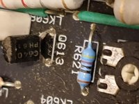
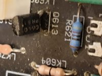
yes, go to page 3 (marking codes) underPhilips BC640")
BC640 pdf, BC640 description, BC640 datasheets, BC640 view ::: ALLDATASHEET :::
I'm fixing the same amp (A1 MK1). I found this thread because I was looking for the spec. of the transformer. I've managed to get a 24 x 2 120VA unit, but when I came to install it I realised that the supply caps are rated at 35V
Max voltage for 24V AC = 24 x 1.41 = 33.84V DC which doesn't leave much head room.
considering then that the transformer primaries are actually spec'ed and 230v the output is going to be 35.36V. which is 34v when you take into account the rectifying diodes.
if you want to run the caps at 80% of the rated voltage (35 x 0.8 = 28V) then this would suggest the transformer should be 20v
I am now thinking that maybe I should have got a 20v, or actually the next one down 18V
supply = 18/230*240 x1.41 = 26.4v
Hi everybody
Just got another A1 MK1 from a charity shop that was declared DOA but bought it anyway (cheap)
After initial tests found the transformer to be cocked and after removal noticed that there is no insulation rubber disc under the toroid so will be looking for one in the 20 to 24Vac (120VA) if someone has one lying about.
To Antspants
Did you managed to get yours going ?
To markywb
The original transformer is 24/0/24Vac I'm 100% sure just checked last night on my working one.
Many amps have very little or no headroom on the filter caps.
1 year old posts how time flies...
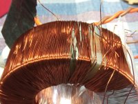
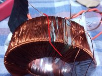
I had to find out "Why" they fail so much (the transformers) in this amplifier model and all 3 versions of it so I had a poke around with this toroid before it goes in the bin...
Enamel failure right under the card with the thermal fuse and lead connections (just a few turns from the start of the winding).
The winding is very poor with wires crossing on top of each other.
Enamel failure right under the card with the thermal fuse and lead connections (just a few turns from the start of the winding).
The winding is very poor with wires crossing on top of each other.
Attachments

OMG!.... you'd have to be intent on sabotage to do something that badly. Either that or QC in the factory was non-existent. I've bought quite a number of new equipment and replacement toroidal trannies from India, HK, China, European countries and UK - lifted the label too but never seen any wiring done that haphazardly.
So, that's the standard Cambridge Audio found acceptable for their A series, eh?
So, that's the standard Cambridge Audio found acceptable for their A series, eh?
That big gap there was me looking for the damage had to remove a few turns.
The fault was in the first layer (closes to the core) and the 3rd pic is self explanatory.
Just remember this amp is over 30 years old and made with parts from the lowest quote.
Now I may need some help with fitting a 18/0/18Vac transformer in it it may need a few resistor changing and I am a knob at it.
Assuming this Mk1 version is Mike Creek's design with discrete semis, we still don't have a schematic to refer to. As it isn't something CA produced or contracted, it can't be covered by their copyright, making the legalities a bit difficult, I guess. Can you trace out the power supplies, at least as far as those (dropping?) resistors and their loads are concerned? I'm sure I've seen the original or something claimed to be close to it, somewhere on the web but not this time around.
Last edited:
Perhaps it's similar to this one: https://www.diyaudio.com/community/threads/creek-5050-schematic.285642/page-2
See #23
See #23
Fitted transformer yesterday and after some a bit of faf it is in and working (new one had dual primaries ).
Primary is 2x115Vac but since power around my area is always over 240V (245 actually) the output is transformer is 20.5Vac or around 27VDC so not to far from the 32 the other A1 with original transformer is delivering.
First note, idle current is down in single digits (low single digit) one channel at 0.7 and the other one at 1.8mw at the 0.22 ohm resistors.
Didn't test any further because wife needed the kitchen table.
Ian that schematic looks close but no cigar the most obvious is the missing fuse by the output devices but will have a better look later today.
That shouldn't surprise. I doubt Cambridge would simply have replicated Creek's design in their own products. Managements generally insist on reducing (in their view) unessential costs to meet some target and 2 fuses + holders probably added significant cost. I imagine there were more corners cut in their cloning process too.
- Home
- Amplifiers
- Solid State
- Cambridge audio a1 mk1 not powering on.