Hi,
When I turn this 1960's (?) Record Deck on, it gives a loud buzzing noise over the speakers. It increases with volume. I can plug my phone into the radio jack (and play music), and play a record on the deck, and the sound comes out, but there's always the loud buzzing noise.
I've got the speed changer, and turntable etc to work, and would like to get it cleaned up and fully working, as it could look lovely. However I don't have the electronic ability to fault find it. I do have the ability to use a multi-meter and do the odd bit of soldering etc, so would like to "have a go".
Does anyone think if I change the capacitors in the attached photos I may stand a chance of curing the buzzing noise? I don't want to throw a lot of money at it, or sub it out to someone (and have to pay them), and if it stands a decent chance, I'd like to give it a try.
I've also put a copy of this post in the analogue source section, as there may be a lot of experience there too.
Thanks, Rob
Attachments
The electrolytics all look good, not saying they are though.
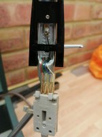
Sounds like you could have a bad earth wire on the cartridge/deck somewhere.
They are very simple to work on, once you have them opened up.
Disconnect the record player from the amplifier end, if the hum has gone, there is the fault, as described above.
If the capacitors were at fault, the hum level would not change with the volume control.
Please see the attached pictures.
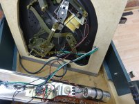
I have tried disconnecting the wiring at the cartridge end, and at the connector on the underneath of the deck, but there was no change in the loud hum. I've also tried wiggling various things and tapping them, with still no change.
I guess the next thing is to try changing the capacitors as suggested.
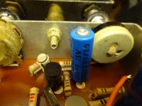
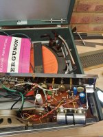
Are the large ones in my pictures the only ones to replace (at first), and are they electrolytics?
Could someone let me know exactly what I should order up please, and would RS (in the UK) be the place to order them? Here's a list of the big capacitors currently in the amp.
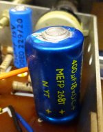
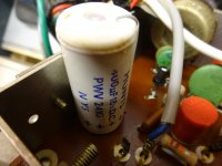
Big white one - Hunts, 400uF, 18V.
Big blue one - Hunts, 400uF, 18V.
Small (ish) blue one - Daly, 250uF, 15V.
Huge silver one - Daly, 2000uF, 30V.
I know it's been suggested going up in capacitance, and voltage, but I could do with a bit of a steer and hand holding")
Thanks, Rob
I have tried disconnecting the wiring at the cartridge end, and at the connector on the underneath of the deck, but there was no change in the loud hum. I've also tried wiggling various things and tapping them, with still no change.
I guess the next thing is to try changing the capacitors as suggested.
Are the large ones in my pictures the only ones to replace (at first), and are they electrolytics?
Could someone let me know exactly what I should order up please, and would RS (in the UK) be the place to order them? Here's a list of the big capacitors currently in the amp.
Big white one - Hunts, 400uF, 18V.
Big blue one - Hunts, 400uF, 18V.
Small (ish) blue one - Daly, 250uF, 15V.
Huge silver one - Daly, 2000uF, 30V.
I know it's been suggested going up in capacitance, and voltage, but I could do with a bit of a steer and hand holding
Thanks, Rob
Attachments

Might be worth getting the service data: 3020 | Ferguson | Manufacturers E to F | Instant Downloads | Home | UK Vintage Radio Service Data
The caps you have illustrated are indeed electrolytic types and the first to replace.
RS is a good place from which to order replacement capacitors.
I would stick as closely as possible to the original capacitance and voltage values. Higher rating rather than lower, especially with voltage rating.
The caps you have illustrated are indeed electrolytic types and the first to replace.
RS is a good place from which to order replacement capacitors.
I would stick as closely as possible to the original capacitance and voltage values. Higher rating rather than lower, especially with voltage rating.
cpc is another supplier: https://cpc.farnell.com/c/electroni...tors/leaded-aluminium-electrolytic-capacitors
e.g. You can replace the two 400uF 18V with these: https://cpc.farnell.com/panasonic/eeufc1e471/capacitor-470uf-25v/dp/CA05153
e.g. You can replace the two 400uF 18V with these: https://cpc.farnell.com/panasonic/eeufc1e471/capacitor-470uf-25v/dp/CA05153
Last edited:
This will replace the 250uF, 15V: https://cpc.farnell.com/panasonic/eeufc1e221/capacitor-220uf-25v/dp/CA05151
This will replace the 2000uF, 30V: https://cpc.farnell.com/panasonic/eca1vam222x/capacitor-2200uf-35v/dp/CA05751
This will replace the 2000uF, 30V: https://cpc.farnell.com/panasonic/eca1vam222x/capacitor-2200uf-35v/dp/CA05751
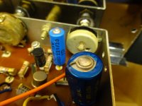
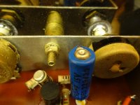
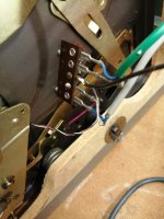
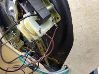
The selenium rectifier is the 'stacked plate' device situated to the left of the big 2000uF capacitor.
The brown wires carry the AC in and the black and red wires carry the DC out of the rectifier.
These age and become less effective. I agree that it is something to look at after replacing the capacitors.
The brown wires carry the AC in and the black and red wires carry the DC out of the rectifier.
These age and become less effective. I agree that it is something to look at after replacing the capacitors.
Attachments
They also let a fair amount of ripple through which may be the source of the hum.
Almost any will do
KBPC3504 Graetz Bridge Rectifier Diodes 35A 400V | eBay
Massive overkill but you could use the fixing holes
Andy
.
Almost any will do
KBPC3504 Graetz Bridge Rectifier Diodes 35A 400V | eBay
Massive overkill but you could use the fixing holes
Andy
.
I was thinking along the same lines!Massive overkill but you could use the fixing holes
Selenium rectifiers will fail eventually, so are best replaced as a matter of course.
Andy, would you consider that the smaller voltage drop of the replacement silicon rectifier would pose a problem in regards to producing a higher DC voltage in this circuit?
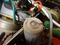
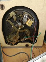
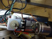
Rob, could you post pictures which clearly show the wiring to and from the selenium rectifier? Just want to make sure we put the right things in the right place!
Attached are the pics requested.
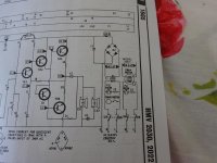
On the schematic its the wiring diagram on the far right that applies to my model (3020). Looks like they're using the motor as a transformer combined.
Would the rectifier on Ebay that was suggested be okay to use? Or any that have free postage
Thanks, Rob
On the schematic its the wiring diagram on the far right that applies to my model (3020). Looks like they're using the motor as a transformer combined.
Would the rectifier on Ebay that was suggested be okay to use? Or any that have free postage
Thanks, Rob
Attachments

Hi.
Yes, they are using the motor as a transformer but this is not a problem. Just cost saving.
Any rectifier will do as long as it has a voltage of around 200v and around 3amps current capacity.
The one from EBAY was the cheapest UK one of that type.
If you have a repair shop near, you could take a printout of the photo and try them.
I used to get similar from Flymo mowers!!!
As I said , any will do as long as they have the voltage and current rating.
The block ones are easier to solder.
PS. The amplifier is what I expected and should be easy to service in the future. Around 6 watts of output.
Andy
.
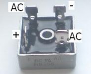
The bridge rectifier (I advise this type because you can simply bolt it in place) is wired as shown in the attachment.
i.e. The brown wires in your record player go to the AC terminals, the red wire to + and the black wire to -.
Remove the short length of red wire which currently connects to the mounting bolt of the selenium rectifier.
i.e. The brown wires in your record player go to the AC terminals, the red wire to + and the black wire to -.
Remove the short length of red wire which currently connects to the mounting bolt of the selenium rectifier.
Attachments
I just wanted to check a couple of things.
The newer capacitors I've bought have the shorter lead marked with minus (-), so I presume the longer lead is the positive (+) lead? On the original capacitors I presume the positive lead is the one that goes to the red insulation on the capacitor? So the longer lead on the new capacitors goes to the same spot that the red insulated lead went to on the old capacitors? Does that sound correct??
Also Galu has said in his post not to connect the red lead that goes to the large capacitor and the chassis earth. Do I have to do any other earthing instead?
Thanks, Rob
Attachments
- Status
- This old topic is closed. If you want to reopen this topic, contact a moderator using the "Report Post" button.
- Home
- Amplifiers
- Solid State
- Loud buzzing on Ferguson 3020/Garrard 3000 Vintage Record Player