Good to see you Lineup, welcome back!
Your amp topology was published in 1972 with Hitachi when they released their famous lateral mosfets (2SK134, 2SKJ49 IIRC), and became pretty much the base for most PA amplifiers, and many domestic amps too. It's a good topology!
From my experience using a single zener as the bias generator and no source resistors will bring thermal runaway at the output stage. I have found with hexfets that the bias generator should be a composite of a 4.7V zener in series with a Vbe multiplier (which drops 3.5V) and the Vbe multiplier should be a BD139 thermally bonded to one of the output devices. This controls the bias very nicely, even with low source resistors.
Hugh
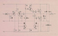
I've been working on something pretty similar.
Main differences:
Cheers,
Jeff.
Main differences:
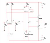
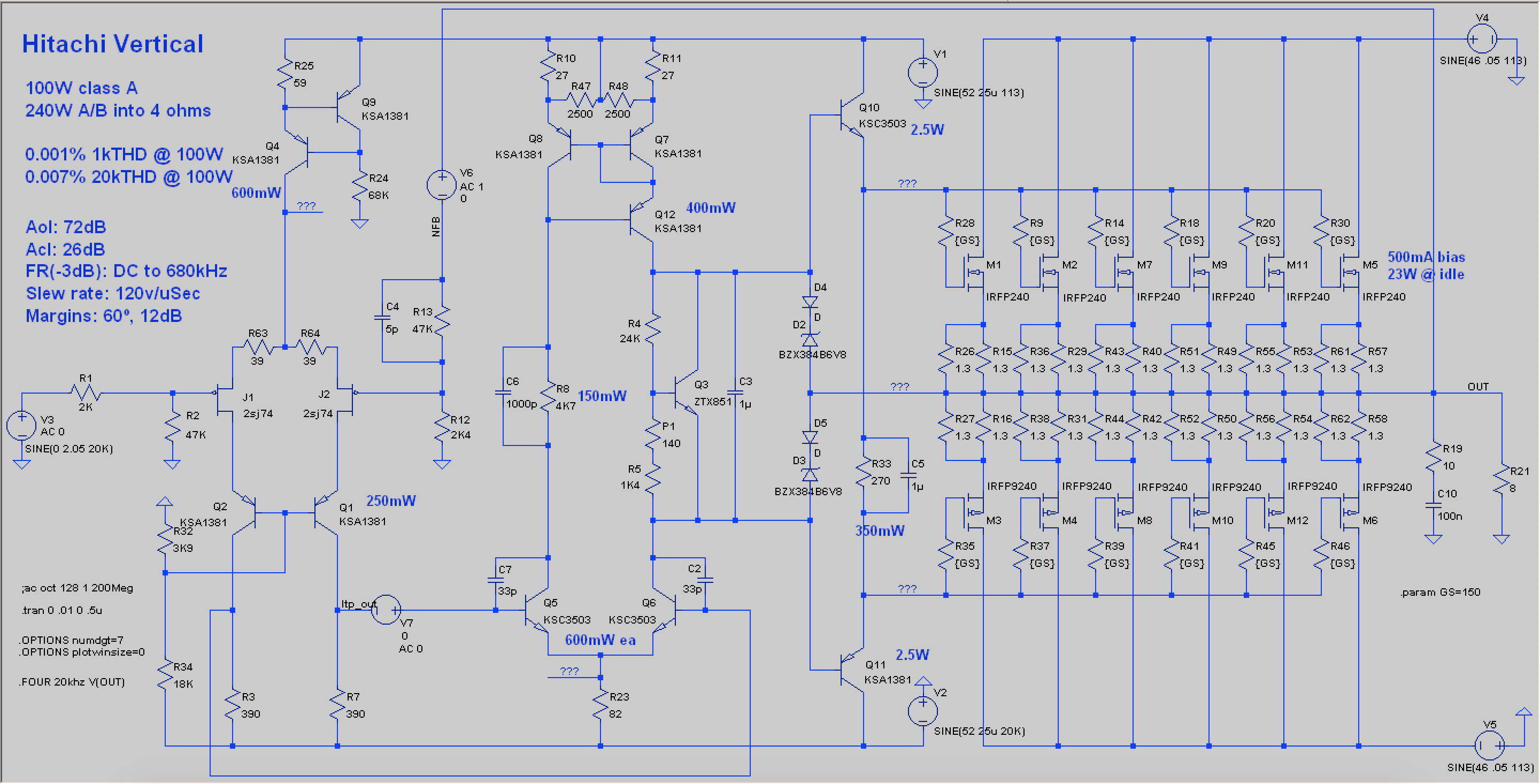
- I'm using a JFET IPS (which also means I had to cascode it).
- I'm using a Wilson current mirror (with a potentiometer for DC offset adjustment).
- I'm using a BJT bias spreader.
- I've also got a pile of 240s/9240s so I needed drivers to keep the slew rate up.
Cheers,
Jeff.
Attachments
@AKSA
Thanks for some history.
I was inspired by MAPLIN MOSFET Kit.
So, I realize this is not at all something new.
The difference is only in small details.
And I am using a VBE-multiplier. One BD139 to sense the heat.
I will publish my full schematic later.
@JeffYoung
Yes, that is pretty much the same design.
But I only have one pair off IRFP240/9240.
Thanks for your schematic.
- Status
- This old topic is closed. If you want to reopen this topic, contact a moderator using the "Report Post" button.
- Home
- Amplifiers
- Solid State
- Simple 100 Watt MOSFET using Dual Pairs of IRFP240/9240