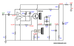
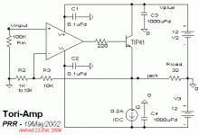
I've finished constructing a simple SE SS amplifier, see attached schematic, from here: A Failed Successful Experiment.
Powered it up, checked voltages, all looked good. When listening to it I heard a high pitched whine which made me think it was oscillating. Put it on the scope and yes, oscillations. With NE5534 in place oscillations are at 1MHz, with a TL071 350kHz, and with a OPA227 1.4MHz.
Supply decoupling is good (100nF right at the power pin and 100uF a centimeter away). What should the next troubleshooting step be? A small cap across the feedback resistor?
Thank you!

Try disconnecting the signal feeding the TIP31C base. Scope the op-amp output for the presence of oscillation. If the output is clean (which it should be), the output transistor circuit may be the problem. Perhaps, the base input circuit of the transistor features too much parasitic capacitance, I don't know. Try could replacing the TIP31C with another NPN power device, or perhaps a power darlington NPN device.
Alternatively, you could try adding a small amount of capacitance between the op-amp's output and inverting input pins to try and compensate for any phase shift that may be stemming from driving the output circuit. Should it still oscillate, even with the power TIP31C removed from the circuit, the layout of the feedback signal path may need to be shortened or possibly rerouted.
Alternatively, you could try adding a small amount of capacitance between the op-amp's output and inverting input pins to try and compensate for any phase shift that may be stemming from driving the output circuit. Should it still oscillate, even with the power TIP31C removed from the circuit, the layout of the feedback signal path may need to be shortened or possibly rerouted.
The op amp is driving a large capacitive load thru the base-emitter junction, this load can be a source of oscillation. Certainly makes any op amp struggle. Needs a base resistor to isolate it and probably compensation across Rf. The NE5534 has compensation pins, use them.
Connecting Rf to the op amp output in this type of circuit worries me - perhaps it should connect to the transistor emitter and include it in the feedback loop. Also the 1meg bias resistor on the non-inverting input is far too large for the typical input bias current - reduce it to the parallel combination of Rf and Rg to minimise bias voltage errors and especially capacitive coupling to the output (another cause of oscillation).
Connecting Rf to the op amp output in this type of circuit worries me - perhaps it should connect to the transistor emitter and include it in the feedback loop. Also the 1meg bias resistor on the non-inverting input is far too large for the typical input bias current - reduce it to the parallel combination of Rf and Rg to minimise bias voltage errors and especially capacitive coupling to the output (another cause of oscillation).
Thank you kindly for all the advice folks 
I soldered in a 22ohm base resistor which cleared up the oscillations on NE5534 completely. Unfortunately it still happens with a OPA134, TL071 and OPA227. 33pF on Rf doesn't help, not does 10k 220pF RC across +/- inputs. I'll continue to try some of the other suggestions made here.
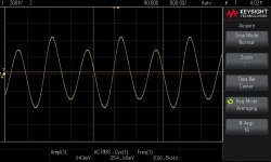
Attached is scope shot from OPA134

try 100r base resistor.
That sorted it out, thank you!
I've now encountered the next problem - there is a large voltage at the input, high as 8V. Is this from the input capacitor charging up? Do I need to worry about it?
Try a base resistor on the TIP, 10R to 47R....
This has worked for several people. (The exact value is not too important.)
Attachments
if you put a resistor to ground on the input it will discharge the capacitor.
try 100k
All sorted and working perfectly!
Thank you everyone for the input!
- Status
- This old topic is closed. If you want to reopen this topic, contact a moderator using the "Report Post" button.
- Home
- Amplifiers
- Solid State
- Op amp oscillation advice
