Hello everyone!
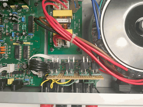
In my livingroom/secondary Stereo set (which I use for Satellite TV & Radio tone, some occational Phono, CD and streaming) I usie a MusicHall Trio (original version, not mk2!). The really cheap Omron relays in this receiver need replacement from time to time which brought me to the idea to use SSRs instead of adapting good but expensive Relays.
The SSRs as such are not between me and success, but the schematic of the Power Output section seems not available anywhere. MusicHall themselves do not cooperate at all. So, if anyone has or knows where to get a schematic, please drop me a private message!
If schematic fails, I'll have to continue reverse engineering the output section which is partially done. Interesting outcome is so far: The Muting function uses a dedicated (Stereo) relay just at the power amp outputs, then loooong PCB traces lead to a speaker terminal board (with a connection cable) which switches two Speaker groups: A/B/A&B. Effectively, for each speaker two Relays' contacts are connected in series!
I don't understand the rationale behind this, as in my view doing Group switch and Muting could be done with simple logic ICs or even with software: Currently, the sytem control Microcontroller outputs directly connect relay drive Transistors to switch the Relays...
Long story cut short: I want to get rid of the cheapo-Omrons and the weird Mute/Group logic, but would like to verify my ideas with the schematic. So if anyone can help, please PM me.
Thanks and Regards,
Winfried
PS: If there's interest expressed in my project, I'm willing to share here
Last edited:
Seems odd for sure.If schematic fails, I'll have to continue reverse engineering the output section which is partially done. Interesting outcome is so far: The Muting function uses a dedicated (Stereo) relay just at the power amp outputs, then loooong PCB traces lead to a speaker terminal board (with a connection cable) which switches two Speaker groups: A/B/A&B. Effectively, for each speaker two Relays' contacts are connected in series!
I don't understand the rationale behind this, as in my view doing Group switch and Muting could be done with simple logic ICs or even with software: Currently, the sytem control Microcontroller outputs directly connect relay drive Transistors to switch the Relays...
One possible idea - what are they doing with the headphone output?
@ sgrossklass
Thanks for your hint at the headphone jack! As I don't usually listen with headphones I actually had forgotten about its existance...
I'll have a look at the board to analyse that circuit part.
BTW: MusicHall did not care to respond to my request at all, their distributor in Germany told me (with kind words) that I don't stand a chance to get any technical info, let alone a schematic. Oh well
Greetings,
Winfried
Thanks for your hint at the headphone jack! As I don't usually listen with headphones I actually had forgotten about its existance...
I'll have a look at the board to analyse that circuit part.
BTW: MusicHall did not care to respond to my request at all, their distributor in Germany told me (with kind words
) that I don't stand a chance to get any technical info, let alone a schematic. Oh well Greetings,
Winfried
OK,. There actually IS an additional, dedicated Headphones Relay seemingly controlled by Muting (tracing is a bit hard on the Image I have), so, this will obviously stay.
Looking at the Muting & Group Switching logic again, I still do not find a necessity or rationale for the original Speaker switching circuitry with two relay's contacts in series...
Therefore I'm designing a simple gate logic, combining Muting and Speaker Group to control switching of the Speaker Outputs.
Greetings,
Winfried
Hi Folks,
despite limited responses I'll finish off this thread so future readers may find it useful or readers frustrated with relay contact "failure" may be inspired by this project.
Firstly a correction: As described, there are three relays (i.e. 2 contacts in series per L and R) in the path from the Power Amp Output to the Speaker Connectors. The first relay is switched on after Power On Delay and not operated by the Muting function! The reasoning of the serial contacts instead of applying output logic remains a mystery to me.
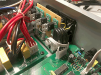
Well, I have now modified the Speaker Output board (a small board, separate from the main PCB and connected by cables):
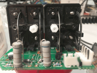
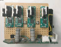
First the OMRON relays had to go and four little SSR boards, based on Si8752 were placed side by side on a piece of experiment PCB.
The plastic holders of the speaker connectors have spare holes which enable fastening the SSR carrier board to them by M3 screws (lucky! )
A bunch of wires were used to connect the SSRs to the respective relay coil connectors (i.e. the relay driver transistor collectors and the 680Ohms/3W Resistors. A 6k8 resistor on each SSR provides 5mA per Si8752 "Diode Input" for fast enough MOSFET switching.


This thing works since a few days now
Next step is to remove the Power On Delayed Relay and bridge the former relay contacts. The relay will be used to provide an OFF level (Gnd) to the Group A/B switch transistor bases (on the speaker connector board) during power on and after that delay connect the Group A/B signals from the microcontroller to the switching transistor bases. So, effectively, the same logic is applied to the speaker outputs as before, but without relay contacts and only one SSR switch (<10mOhm) in the power signal path.
Last plan is to (solder)connect the power amp outputs directly to the SSR power inputs by solid core wires instead of the long, thin main PCB traces, crimped cable pieces and connectors, so the low SSR on-resistance actually makes more sense...
So much for the moment...

Winfried
despite limited responses I'll finish off this thread so future readers may find it useful
or readers frustrated with relay contact "failure" may be inspired by this project. Firstly a correction: As described, there are three relays (i.e. 2 contacts in series per L and R) in the path from the Power Amp Output to the Speaker Connectors. The first relay is switched on after Power On Delay and not operated by the Muting function! The reasoning of the serial contacts instead of applying output logic remains a mystery to me.
Well, I have now modified the Speaker Output board (a small board, separate from the main PCB and connected by cables):
First the OMRON relays had to go and four little SSR boards, based on Si8752 were placed side by side on a piece of experiment PCB.
The plastic holders of the speaker connectors have spare holes which enable fastening the SSR carrier board to them by M3 screws (lucky!
)A bunch of wires were used to connect the SSRs to the respective relay coil connectors (i.e. the relay driver transistor collectors and the 680Ohms/3W Resistors. A 6k8 resistor on each SSR provides 5mA per Si8752 "Diode Input" for fast enough MOSFET switching.
This thing works since a few days now
Next step is to remove the Power On Delayed Relay and bridge the former relay contacts. The relay will be used to provide an OFF level (Gnd) to the Group A/B switch transistor bases (on the speaker connector board) during power on and after that delay connect the Group A/B signals from the microcontroller to the switching transistor bases. So, effectively, the same logic is applied to the speaker outputs as before, but without relay contacts and only one SSR switch (<10mOhm) in the power signal path.
Last plan is to (solder)connect the power amp outputs directly to the SSR power inputs by solid core wires instead of the long, thin main PCB traces, crimped cable pieces and connectors, so the low SSR on-resistance actually makes more sense...
So much for the moment...
Winfried
Attachments

- Status
- This old topic is closed. If you want to reopen this topic, contact a moderator using the "Report Post" button.