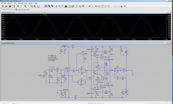
I found this amp in old Radio magazine (in Russian).
It looks interesting (Vbe multiplier arrangement, VAS),
so I tried to sim it. The results don't look bad.
Has anybody seen a similar amp before?
I had to make some changes (hopefully 'improvements'),
as the original amp was clipping too soon, and bias settings
couldn't be made to work..
Sim files with models attached.
===========================
Update: This thread continued with similar amps to this one, namely Wiederhold amp from 1977, and its derivatives.
What's common to all of them is: op-amp input and folded cascode VAS.
As of Jan 2024, based on this thread, over 15 amps have been 'officially' successfully built and tested (plus several prototypes).
1) Posts #87, #117, #136 - LMK (Lomakin & Parshin) complementary BJT
2) Posts #172, #201, #206 , #1449 - complementary LatFet Wiederhold77
3) Posts #326, #313, #1735 - quasi HexFet Wiederhold77
4) Posts #952, #985, #1065 - quasi BJT Wiederhold77 with 2n3055 devices
5) Thread LatFet Amps Based on Philips AH578
6) Post #1537 , #1471, #1568 - high power and improved version of LMK amp with FQA vertical mosfets (3 pairs)
7) Post #111 (in another thread) - high power symmetrical LMK-type amp with Philips AH578 input stage
8) LMK-type with Groner input stage built in April 2022
9) Alexander-type amp with folded cascode VAS - post #1676
10) Darlington-type VAS - post #1699
11) Post #1706 - LMK complementary BJT with TIP3055/2955
12) Post #1709 - Hafler P7000 inspired amp
13) Post #1736 - mirror VAS with interesting compensation
14) Post #1735, #1744 - quasi HUF logical level fets Wiederhold77
15) Post #1745 , #1746 - 'improved' Hafler P7000 with (Hawksford Cascode)
Attachments
Last edited:
I haven't seen it before, but it looks a bit scary to me. The output transistors have no emitter resistors, so there is no local feedback to reduce the effect of temperature tracking errors between VT3/VT4 and VT8/VT9 on the quiescent current. Your modifications make it worse by also making it sensitive to the temperature of Q5. I don't see any reason why you couldn't add emitter resistors to VT8/VT9 if needed for thermal stability, though.
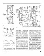
Transistor VT4 germanium RF.
A similar displacement scheme was used in a number of designs by Dr. Igor Akulinichev. He called the current shunt circuit
Стр. 26 журнала <<Радио>> № 4 за 1979 год
Стр. 57 журнала <<Радио>> № 10 за 1989 год
Стр. 22 журнала <<Радио>> № 1 за 1993 год
A similar displacement scheme was used in a number of designs by Dr. Igor Akulinichev. He called the current shunt circuit
Стр. 26 журнала <<Радио>> № 4 за 1979 год
Стр. 57 журнала <<Радио>> № 10 за 1989 год
Стр. 22 журнала <<Радио>> № 1 за 1993 год
Last edited:
I haven't seen it before, but it looks a bit scary to me. The output transistors have no emitter resistors, so there is no local feedback to reduce the effect of temperature tracking errors between VT3/VT4 and VT8/VT9 on the quiescent current. Your modifications make it worse by also making it sensitive to the temperature of Q5. I don't see any reason why you couldn't add emitter resistors to VT8/VT9 if needed for thermal stability, though.
I'm sure I can, but but my 1st goal was to reproduce this amp "as is", and then
think what's wrong with it.
I only made changes that I had to do, to make it work at all.
Last edited:
I see Dr. Igor Akulinichev doesn't use emitter resistors in any of his designs...
And he's also using the same biasing in all designs.
OldDIY - you must have memorized all Radio articles, to find them so quickly")
I start seeing a pattern here: Russian transistor names that start with 'g' are germanium,
and these with 'k' are silicon, right?
And he's also using the same biasing in all designs.
OldDIY - you must have memorized all Radio articles, to find them so quickly
I start seeing a pattern here: Russian transistor names that start with 'g' are germanium,
and these with 'k' are silicon, right?
Last edited:
The scheme looks very clever, and I wouldn't dismiss it just based on the look of the thermal compensation.
There are a number of layers, and they all have to be carefully examined and analyzed before a conclusion can be drawn.
It should be possible to keep the original circuit with Si-only transistors, which looks essential to retain the original properties
There are a number of layers, and they all have to be carefully examined and analyzed before a conclusion can be drawn.
It should be possible to keep the original circuit with Si-only transistors, which looks essential to retain the original properties
I'm sure I can, but but my 1st goal was to reproduce this amp "as is", and then
think what's wrong with it.
I only made changes that I had to do, to make it work at all.
Fair enough; as long as you're only simulating, there are no thermal tracking issues anyway.
Does Dr. Akulinichev do anything special to get good thermal tracking? Or is the trick in the use of a silicon and a germanium device, does that for some reason result in a somewhat stronger temperature dependence of the voltage of the VBE multiplier than only silicon?
Russian stuff, Old diy, where can I buy a couple of AK 47 valves
In Soweto obviously. Or in Alex. More importantly, they also offer daily rentals, so you can make up you mind if you enjoy them in your own system. After the booze ban ends of course

>Does Dr. Akulinichev do anything special to get good thermal tracking?
I guess I'll grab a dictionary, and try to understand the whole article from the Radio magazine. May take a while
They write that the effect of combining a logarithmic dependence for Si and linear for Ge.
Transistor shunt, controlling the voltage at the bases. To stabilize the current output transistors and damping switching processes.
Current feedback, providing output transistors with 0 current. (Dr. Akulinichev)
Last edited:
- Home
- Amplifiers
- Solid State
- Unusual amp from 1987