Please give a link to these amplifiersI'm wondering about one thing: someone said previously in this thread, that amps with this kind vas (cascode) don't need to have slew rate as high as blameless amps. Is that actually true, and why ?
=====================
Меня интересует одна вещь: кто-то сказал ранее в этой теме, что усилители с таким типом VAS (каскодом) не должны иметь такую высокую скорость нарастания,
как безупречные усилители.
Это правда и почему?
I was talking about amps such as LMK, Wiederhold, where VAS stage is UNLIKE VAS in blameless amp, and voltage amplification comes as a result of high impedance node being driven by input stage via emitter of the transistor.
So most of amps from this thread qualify as such.
So most of amps from this thread qualify as such.
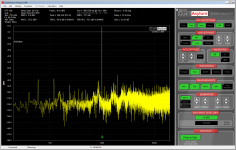
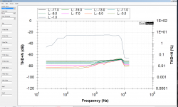
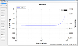
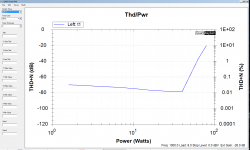
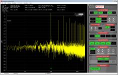
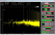
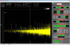
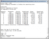
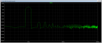
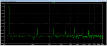
After testing LatFet version of Wiederhold amp, today I tried to test Quasi BJT version with 2N3055 output devices, built for nostalgic reasons (from post #952)
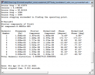
In the listening test I can't tell these amps apart.
PSU was +/- 20V, load 8 Ohms.
Here are the results.
Screen #7 is for 1kHz, screen #8 for 10kHz
Up till 18W Thd is not bad, but from there, it gets worse (It would be better with rails +/- 25V).
Conclusion: there is a big difference between cheap quasi amp with 50 cent output devices versus expensive Laterfal Fets
after all")
In the listening test I can't tell these amps apart.
PSU was +/- 20V, load 8 Ohms.
Here are the results.
Screen #7 is for 1kHz, screen #8 for 10kHz
Up till 18W Thd is not bad, but from there, it gets worse (It would be better with rails +/- 25V).
Conclusion: there is a big difference between cheap quasi amp with 50 cent output devices versus expensive Laterfal Fets
after all
Attachments


Last edited:
Maxim,
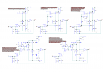
It looks like most of these variations were already tried in this thread...
It also looks like everything is pretty much the same in all these models, except for the biasing (and/or sending some signal)
to the upper-left transistor...
Which model fits this amp ?
HexFet Amp Based on Philips AH578 and LMK
Last edited:
No, the parallel channel was not introduced . This is from here .????????????? ????????? ?? ????????? ??????????? (1977) 2021
Before building symmetrical version of the amp, as described in
this thread: hexfet-amp-based-philips-ah578-lmk,
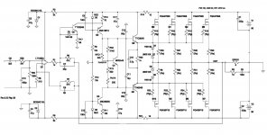
I decided to build one more LMK style of this amp.
Compared to the initial version from post 1, everything is improved, especially stability: PhaseMargin=69, GainMargin=22.
This should make very stable amp. Also, this time, it's done with vertical FETs, instead of BJTs. There are 4 pairs of HexFets in the schematic,
but since I'll be powering this amp with 50V rails, 3 pairs will be enough for me, to get honest 160W, maybe more.
It will work with higher rails with minimal changes.
Idle current (bias) control implemented with NTC thermistor. I used this kind of setup in few other HexFets amps, with great success.
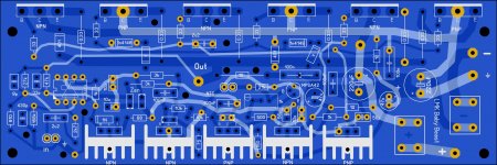
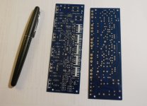
There is a PCB designed in SprintLayout.
I hope to finish both amps before 'going back to office' in September. These are last months of relative freedom of 'working from home' and avoiding wasting 2h40min daily on commute...
this thread: hexfet-amp-based-philips-ah578-lmk,
I decided to build one more LMK style of this amp.
Compared to the initial version from post 1, everything is improved, especially stability: PhaseMargin=69, GainMargin=22.
This should make very stable amp. Also, this time, it's done with vertical FETs, instead of BJTs. There are 4 pairs of HexFets in the schematic,
but since I'll be powering this amp with 50V rails, 3 pairs will be enough for me, to get honest 160W, maybe more.
It will work with higher rails with minimal changes.
Idle current (bias) control implemented with NTC thermistor. I used this kind of setup in few other HexFets amps, with great success.
There is a PCB designed in SprintLayout.
I hope to finish both amps before 'going back to office' in September. These are last months of relative freedom of 'working from home' and avoiding wasting 2h40min daily on commute...
Attachments
Last edited:
No, the parallel channel was not introduced . This is from here .????????????? ????????? ?? ????????? ??????????? (1977) 2021
Maxim, what are you up to recently?
I remember back in Dec you were working on the PCB.
Have you ever complete your build?
========================
Максим, чем ты занимаешься в последнее время? Я помню, еще в декабре вы работали над печатной платой. Вы когда-нибудь завершали свою сборку?
Excellent layout. Waiting for the result. It seems that in addition to HEXFETs, only the thermistor needs to be mounted on the heat sink. How can this be done effectively?
https://www.distrelec.hu/hu/termisztor-ntc-22kohm-41-5mm-epcos-b57891m0223k000/p/16029020
https://www.distrelec.hu/hu/termisztor-ntc-22kohm-41-5mm-epcos-b57891m0223k000/p/16029020
Excellent layout. Waiting for the result. It seems that in addition to HEXFETs, only the thermistor needs to be mounted on the heat sink. How can this be done effectively?
One method I have seen for this is to put the bead of the thermistor inside of a ring terminal, with thermal grease... and then screw the ring terminal to the heatsink
> It seems that in addition to HEXFETs, only the thermistor needs to be mounted on the heat sink. How can this be done effectively?
Correct.
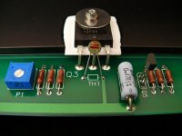
I used this method on 3 amps, so far:
1) I glued the thermistor bead directly to the back of the transistor (with thermal glue)
2) I drilled small hole in the heatsink just next to one of the transistors, and glued the thermistor inside that hole.
3) glued the bead between 2 transistors
Thermistor bead is very small, so 2-3mm hole will suffice.
All methods worked perfectly...
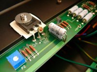
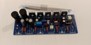
When designing the PCB, I took a hint from Ostripper latest PCB - N and P output devices are interweaving: N-P-N-P-N-P, so supposedly currents flowing between them, will settle in more civilized manner..
Latest schematic/pcb attached. Silk screen layer had some mistakes (e.g. orientation of gate protection diodes).
Correct.
I used this method on 3 amps, so far:
1) I glued the thermistor bead directly to the back of the transistor (with thermal glue)
2) I drilled small hole in the heatsink just next to one of the transistors, and glued the thermistor inside that hole.
3) glued the bead between 2 transistors
Thermistor bead is very small, so 2-3mm hole will suffice.
All methods worked perfectly...
When designing the PCB, I took a hint from Ostripper latest PCB - N and P output devices are interweaving: N-P-N-P-N-P, so supposedly currents flowing between them, will settle in more civilized manner..
Latest schematic/pcb attached. Silk screen layer had some mistakes (e.g. orientation of gate protection diodes).
Attachments
Last edited:
One method I have seen for this is to put the bead of the thermistor inside of a ring terminal, with thermal grease... and then screw the ring terminal to the heatsink
Good idea. Another way to sensoring the output temperature described by Bonsai:
"If using NTC ( or PTC for that matter) PCB mount sensors, you can do better than trying to measure the heatsink temp: you measure the output transistor collector lead temp, which is in effect the die header temp. On a power transistor, the die will only be 1 or 2 degrees hotter and the response of course is very fast."
It seems Mr. Pass uses similar method:
Attachments
Last edited:
That's my thermistor. Smaller.
https://www.mouser.com/ProductDetai...31iyuCjxY1w==&countrycode=US¤cycode=USD
https://www.mouser.com/ProductDetai...31iyuCjxY1w==&countrycode=US¤cycode=USD
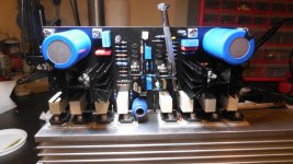
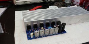
Mosfets matched, amp ready for testing. Will try to do it this weekend..
The idea is that 2 amps will be bolted to 1 heatsink, as shown, one next to each other, and - as usual - whole thing gonna be mounted on top of chassis (this time - wood (African Acacia), not Alu).
Assuming the testing will go well
The idea is that 2 amps will be bolted to 1 heatsink, as shown, one next to each other, and - as usual - whole thing gonna be mounted on top of chassis (this time - wood (African Acacia), not Alu).
Assuming the testing will go well
Attachments
- Home
- Amplifiers
- Solid State
- Unusual amp from 1987