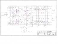
Anybody ever tried cloning this amplifier? I am planning to make a PCB.
Is the schematic correct?
Will it work perfectly after implementation or do I have to change anything? Also, will it make any trouble if I eliminate the servo circuit from the amp?
Due to unavailability of some transistors, I want use 2SC2073/2SA940 pairs throughout the whole design and 2SC5200/2SA1943 for the output pairs.
Waiting for expert's suggestion. Thnx in advance!!
Attachments
I can see why you want to clone it its been called --" a near Krell " some actually prefer it ,powerful bottom end just misses out by a sliver at the top end.
One problem is the DC servo acts as a safety cutout according to the company ,you would of course have to balance the input BJT,s although the 2SC3381 are a dual matched pair as is the 2SA1349 pair so maybe not all that much if the offset is pretty low.
You have considered they are twin dual matched pairs in your choice of replacement BJT,s ?
I can see why you want to clone it its been called --" a near Krell " some actually prefer it ,powerful bottom end just misses out by a sliver at the top end.
One problem is the DC servo acts as a safety cutout according to the company ,you would of course have to balance the input BJT,s although the 2SC3381 are a dual matched pair as is the 2SA1349 pair so maybe not all that much if the offset is pretty low.
You have considered they are twin dual matched pairs in your choice of replacement BJT,s ?
Yes, those dual pairs are not available.
 Although I can match those 2SC2073 and 2SA940 pretty well. These are readily available.
 Would it be wise to use an offset control circuit like those in krell ksa series?
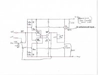
There is also a (perhaps optional) discrete balanced to unbalanced input circuit that precedes the circuitry shown on the schematic attached to the first post. Hand sketch of that circuit attached below
Attachments
Last edited:
There is also a (perhaps optional) discrete balanced to unbalanced input circuit that precedes the circuitry shown on the schematic attached to the first post. Hand sketch of that circuit attached below
Thnx Markw
I appreciate it.How does the DC servo drive the relay? Is there an additional schematic between the servo op-amp output and the relay coil (driver)?One problem is the DC servo acts as a safety cutout according to the company ,you would of course have to balance the input BJT,s although the 2SC3381 are a dual matched pair as is the 2SA1349 pair so maybe not all that much if the offset is pretty low.
In the Aragon 8008 Mkii at my place, the output protection relay is driven by a separate PCB that monitors the DC power rails and the amplifier output. Don't have a schematic, but IIRC it is more or less a typical audio amp output fault detector circuit that observes the amplifier output for any average DC offset. Since it relies on averaging, there can be a short delay before it operates in the event of a fault. The servo op-amp does not directly interface with the protection circuit.
Yes. R21 just sets the diode stack bias current.Is the connection between R20, R21 & R9 a mistake in the schematic? (The schematic in post #1?)
Last edited:
Aside: Aragon 8008 Mkii has a fairly beefy raw power supply with high quality transformers. Also, the PCBs are also laid out in a way that happens work quite well in practice for this amplifier. Output stage is biased somewhat on the hot side to maintain a bit wider than typical class-A operating region. In other words, there are some things not shown on the schematics that might be worth thinking about early on when working out a clone cost estimate, etc. In some cases finding a used amplifier might be cheaper and easier, not sure.
Yes, I already fixed that mistake before making the PCB.Yes. R21 just sets the diode stack bias current.
Can perhaps use an op-amp for this buffer circuit?There is also a (perhaps optional) discrete balanced to unbalanced input circuit that precedes the circuitry shown on the schematic attached to the first post. Hand sketch of that circuit attached below
Thnx. Can you please tell me a little further about some of the parts that are missing in the schematic?Aside: Aragon 8008 Mkii has a fairly beefy raw power supply with high quality transformers. Also, the PCBs are also laid out in a way that happens work quite well in practice for this amplifier. Output stage is biased somewhat on the hot side to maintain a bit wider than typical class-A operating region. In other words, there are some things not shown on the schematics that might be worth thinking about early on when working out a clone cost estimate, etc. In some cases finding a used amplifier might be cheaper and easier, not sure.
Some people might do it, and other people might be concerned the sound would suffer. You could try it both ways and see what you think. My personal choice would be to stay with discrete circuitry.Can perhaps use an op-amp for this buffer circuit?
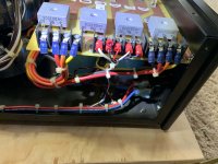
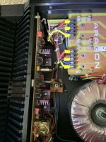
Some pics show components not shown on the schematics.
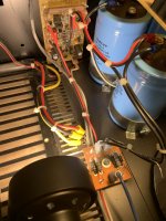
First pic shows one end of the rectifier and filter board.
2nd pic shows the other end of the same board with screws removed that connect the board to the filter caps underneath it. Also in the same pic are two power transformers stacked on top of each other, one for each channel. Also in the 2nd pic, a small white rectangle can be seen sitting sandwiched between one of the amplifier boards and the heatsink. It is a thermal switch in series with R121, although it is not shown on the schematic. The switch is to help protect the amplifier in the event of excessive heatsink temp.
3rd pic shows same area with the rectifier board lifted out of the way. In the top center area is a small PCB with the speaker protection circuit on it. It drives the relays on the two amplifier channel boards to disconnect the speakers in the even of a fault. Schematics for similar boards can probably be found searching around the forum or via google. Lower down on the same pic is a smaller PCB which IIRC is hum breaker circuit. Schematics for typical audio amplifier hum breakers can be found too. Also shown in the 3rd pic are some of the obsolete big filter caps. The wires and lugs sitting on top of some of the cap terminals actually are supposed to connect to the rectifier board that was pulled out of the way to take the pic. Normally the rectifier board is only thing screwed directly to the cap terminals.
Attachments
Last edited:
Thnx Mark. Can you show me the schematic of this hum breaker circuit? Is it sitting on the DC side of the power supply?Some pics show components not shown on the schematics.
First pic shows one end of the rectifier and filter board.
2nd pic shows the other end of the same board with screws removed that connect the board to the filter caps underneath it. Also in the same pic are two power transformers stacked on top of each other, one for each channel. Also in the 2nd pic, a small white rectangle can be seen sitting sandwiched between one of the amplifier boards and the heatsink. It is a thermal switch in series with R121, although it is not shown on the schematic. The switch is to help protect the amplifier in the event of excessive heatsink temp.
3rd pic shows same area with the rectifier board lifted out of the way. In the top center area is a small PCB with the speaker protection circuit on it. It drives the relays on the two amplifier channel boards to disconnect the speakers in the even of a fault. Schematics for similar boards can probably be found searching around the forum or via google. Lower down on the same pic is a smaller PCB which IIRC is hum breaker circuit. Schematics for typical audio amplifier hum breakers can be found too. Also shown in the 3rd pic are some of the obsolete big filter caps. The wires and lugs sitting on top of some of the cap terminals actually are supposed to connect to the rectifier board that was pulled out of the way to take the pic. Normally the rectifier board is only thing screwed directly to the cap terminals.
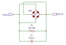
Its effectively about same as the schematic attached below, but without the capacitor. AC line ground connects to the chassis side; amplifier circuit ground connects to the other side of the hum breaker. The resistor value in some amplifiers may be a higher value, have seen 47-ohms or 100-ohms in some designs. The diodes and resistor should be able to handle enough surge current in case of a fault condition so as to allow other protection mechanisms time to act.
Attachments
Last edited:
Thank you so much Mark.. So basically I just need to bias the input stage transistors properly in order to make this amplifier work, except from all the other circuits that we've discussed here, right? Thank you once again!!Its effectively about same as the schematic attached below, but without the capacitor. AC line ground connects to the chassis side; amplifier circuit ground connects to the other side of the hum breaker. The resistor value in some amplifiers may be a higher value, have seen 47-ohms or 100-ohms in some designs. The diodes and resistor should be able to handle enough surge current in case of a fault condition so as to allow other protection mechanisms time to act.
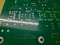
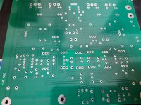
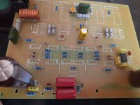
Here are some of the pics of my PCB. Working on it right now!!
Attachments
The hum breaker is not related to input stage bias 
Its just to reduce the tendency of the AC line safety ground to act as a path for noise incursion into the amplifier circuitry common (which might be thought of as sort of a semi-isolated 'ground').
The amplifier's de-balancing circuit on the input is also designed to help reduce ground coupled noise. In the case of unbalanced input connections, the incoming ground from any external preamp is not connected directly to the power amp chassis ground, rather it is processed as a differential signal.
EDIT: Regarding bias, the resistor values shown in the schematics are correct for the types of transistors used in the original amp (don't recall if there was a typo on any resistors). Different transistors may need some tweaking. Regarding output stage bias, IIRC output transistor emitter resistor drops when fully warmed up settle at about 34-35mV.
EDIT2: Just found a note the the current source emitter resistors for de-balancer input stage are actually 2.5k, not 200R as in the main amplifier input stage. Emitter resistors for Q5, Q6 are 10k. Not sure what the other unmarked resistor values are.
Last edited:
- Home
- Amplifiers
- Solid State
- Aragon 8008 clone