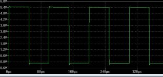
i'm testing a vssa based circuit, however in sims and real life i get a small amount of HF boost as indicated by a 10KHz squarewave.
raising the miller caps to 100pF does not help (and 33p is enough for stable operation)

raising the miller caps to 100pF does not help (and 33p is enough for stable operation)
Attachments
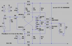
There is not much to the circuit and I recognise raising the comp capacitors values made no difference then try something different that might not look straightforward to some .
Parallel R14/R15 with a very low value (picofarad ) capacitor on you actual built design not a virtual version and report back as to the shape of the 10kHz square wave.
You might need to experiment with the value to get a flat top response .
Parallel R14/R15 with a very low value (picofarad ) capacitor on you actual built design not a virtual version and report back as to the shape of the 10kHz square wave.
You might need to experiment with the value to get a flat top response .
The overshoot is so small (in time and peak value) I wouldn't worry about it, but...
The overshoot appears to damp out with a time constant of about 1 us. R1 C1 is exactly 1 us, and the branch R1 C1 causes a zero in the input to output transfer as well as the loop gain. With the feedback loops closed, some pole is bound to end up right next to the zero and the pole-zero pair then causes a small over- or undershoot that damps out with a time constant close to 1 us.
All in all, can you change the overshoot by tweaking C1?
Last edited:
If it should be related to R1-C1, you might consider using a first-order series filter at the output rather than a Boucherot network (as was proposed by A. N. Thiele decades ago):
Inductor L in parallel with R = 5 ohm between the amplifier output and the load
Capacitor C straight across the 5 ohm load
Choose L = R^2 * C
This only works perfectly when the load is resistive and the load and the resistor across the inductor have equal resistances. Otherwise it works well, but not perfectly.
i'm testing a vssa based circuit, however in sims and real life i get a small amount of HF boost as indicated by a 10KHz squarewave.
raising the miller caps to 100pF does not help (and 33p is enough for stable operation)
What level is your output dc offset? the simulation square wave plot suggests this in not zero. If the simulation is anything to go by the current drawn from the supply rails and the power dissipation are many times greater than what one might expect.
Looks like I didn't read the ctrlx's question in the first place - I see you already tried raising the comp caps - apologies for my oversight!
Leave the comp caps as they are and look at the filter using R6 with a cap to ground from the bases of the input devices I suggested earlier.
Although minimal with a purely resistive load as in the sim, the overshoot may be exacerbated further by reactive loads.
Have you looked at what happens with your circuit when driving a capacitive load?
I'd not be worried, in slew-limiting conditions stability is an issue, but a small amount of overshoot isn't usually a problem - this should never happen in real life signals anyway, especially if the input has a decent RFI filter - the slew-rate is far larger than the minimum necessary for audio.
You say a small amount of HF boost, but you're talking around 1MHz rather than 20kHz I think (what freq response are you seeing? How are the phase/gain margins?)
You say a small amount of HF boost, but you're talking around 1MHz rather than 20kHz I think (what freq response are you seeing? How are the phase/gain margins?)
You know why gate stopper are there Kokoriantz ?
Could you explain your logic ---please ?
Here is a professional electrical engineering website advice on this
notice it reduces the speed and high frequency oscillations especially if long leads are used between the driver and actual gate.-
Could you explain your logic ---please ?
Here is a professional electrical engineering website advice on this
notice it reduces the speed and high frequency oscillations especially if long leads are used between the driver and actual gate.-
- Slow down the switching to reduce EMI.
- Reduce the current spike drawn from the supply during MOSFET turn-on. If local decoupling is not good enough, this current could make VCC sag, triggering the chip's UVLO. Fortunately the chip's pinout makes it easy to achieve a low inductance decoupling.
- In case the layout is suboptimal with a long gate trace. This adds inductance in the gate which can cause the MOSFET to osillate. A resistor will dampen the oscillations, at the cost of slower switching. This is a bit of
- a band-aid, a tight layout is preferable.
- They also reduce Ringing .
Last edited:
That's clearly a site about switched-mode power supplies rather than class-A, -B or -AB amplifiers. The only part of it that is applicable here is the part about preventing oscillations when there is some gate wire inductance.
Excessively large gate stopper resistances could reduce the corner frequency of the MOSFET gate capacitances and their driving impedances, reducing the phase margin of the overall feedback loop. I doubt if that is the case here, though.
Excessively large gate stopper resistances could reduce the corner frequency of the MOSFET gate capacitances and their driving impedances, reducing the phase margin of the overall feedback loop. I doubt if that is the case here, though.
Kokoriantz is looking at the impact of the gate stoppers on the loop stability which is a legitimate concern. This is a completely different thing to parasitic oscillations although one can trigger the other.
That said, reducing the gate stoppers will solve one problem (possibly) and run the risk of introducing another.
I think Mark's comment is spot on. Audio signals are normally band width limited so you are never going to see ultra fast rise times. If you feed ultra fast rise time signals, most amps will show overshoot of some kind unless the amp is preceded by a front end LPF. For the record, JC usually limits the risetimes on his amps to 5-10us. I don't go quite that far, but a 200-300 kHz filter on the front end would cure this issue.
We are talking of overshoot here aren't we not oscillation ?
Loop stability is heavily dependent on the compensation capacitor.
Every build I do I check out the amp by injecting a signal ,usually a high speed one connecting my scope to the output along with my load resistance , running it at low power then half power then full power and watching the output square wave , adjusting the comp capacitor and the other hand on the variac in case of HF oscillation .
On every design variation , usually on JLH designs --mosfet output the compensation required was well under D.Self,s 100pf.
Using this practical method I can watch the overshoot and flatten it off as well as oscillations--bandwidth on one I built was flat to over 100kHz--then dropped down reaching 130kHz .
I used an ex USA military semi variable small value capacitor to find the correct value.
This never let me down , I have never got down to LT Spice as it requires Wine which is associated with MS and I use Linux.
By the way the two gate stoppers are the exact values JLH used.
Last edited:
Right Choice of MOSFET devices?
When I ran the simulation for this the output dc offset was -27 V.
Swapping out the SK and SJ Mosfets for IRP240N and IRFP9240P reduced this to -106 m.V.
The simulation looks a bit better with equal value stopper resistors and a change in the value of R12 to trim the output dc offset -see revised .asc
The standing current of the output stage is low but I leave this and other refinements to others.
Attachments
i'm testing a vssa based circuit, however in sims and real life i get a small amount of HF boost as indicated by a 10KHz squarewave.
raising the miller caps to 100pF does not help (and 33p is enough for stable operation)
There is a series RCR circuit between R8-R9
- Status
- This old topic is closed. If you want to reopen this topic, contact a moderator using the "Report Post" button.
- Home
- Amplifiers
- Solid State
- vssa squarewave response