SCA v1.2
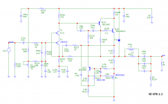
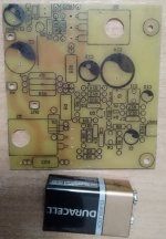
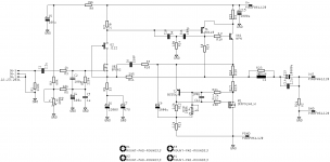
Single ended Current Feedback Amplifier.
It could be done with various power supply voltages and bias cureents, this is just an example I`m testing and listening for months now..
No thump at start up (if all caps are disscharged). No noise or hum of any kind with sensitive speakers 97dB.
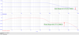
Some measurements in a few days.
Single ended Current Feedback Amplifier.
It could be done with various power supply voltages and bias cureents, this is just an example I`m testing and listening for months now..
No thump at start up (if all caps are disscharged). No noise or hum of any kind with sensitive speakers 97dB.
Some measurements in a few days.
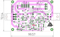
Attachments
Last edited:
All "critical" resistors and compensation caps on proto could be changed quick, so I will experiment with values if you have any suggestions.
R208 is shorted and it could be some small value, up to 0.5 or 1R (with R205 value adjusted) for higher output impedance, or lower dumping factor.
For now it`s like in the schematic.
R208 is shorted and it could be some small value, up to 0.5 or 1R (with R205 value adjusted) for higher output impedance, or lower dumping factor.
For now it`s like in the schematic.
Why use low voltage MOSFET +jFET ? I used ssm3k339 alone.
NEW class A :Constant Current Push Pull amplifier with single SMPS and hybrid preamp
At 2ma , it has a Gm of 40mS vs 2mS.
NEW class A :Constant Current Push Pull amplifier with single SMPS and hybrid preamp
At 2ma , it has a Gm of 40mS vs 2mS.
Last edited:
Why use low voltage MOSFET +jFET ? I used ssm3k339 alone.
NEW class A :Constant Current Push Pull amplifier with single SMPS and hybrid preamp
At 2ma , it has a Gm of 40mS vs 2mS.
I'm not really shure, what you wanted to say? Input jfet is cascoded, 2SK932 it's a great part, but Vds is only 15V max. J112 is simple solution for cascode, giving constant, "floating" Vds for lower jfet, of about 2V7.
Output stage is half bjt CFP, like in Hiraga amps and another half is modulated mosfet ccs similar to FW amps. .
Wonderfully asymmetrical Class A using outstanding diverse approach, excellent compensation and even tube source fb from output. Original!
How's it sound?
HD
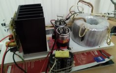
The sound is very nice, i'm currently listening only one chanel, mono (left and right speaker in parallel).
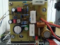
Btw, something interesting, power supply is a plain diode bridge and one 15mF elna cap, the circuit has decent PSRR. When speaker GND wire is connected to the power supply star ground there is a slight hum/buzz, with ears close to speakers, and with speaker GND wire, connected to pcb star ground, all that is gone and speakers are silent.
Good idea and nice asymmetric design, looking forward to see some real measurements
Can you tell what difference changing R208 makes?
And can you tell what changes you would suggest for 4 ohms load, and what power can be expected into 8 ohms and 4 ohms with one BJT and one MOSFET?
Can you tell what difference changing R208 makes?
And can you tell what changes you would suggest for 4 ohms load, and what power can be expected into 8 ohms and 4 ohms with one BJT and one MOSFET?
Member
Joined 2009
Paid Member
I love it - this is a very nice looking amplifier schematic. I was surprised by the two pole compensation around one device - in that I've found in simulations that it's been necessary to use a compound (two device) VAS to be needed for full benefit from two-pole taken around it - but simulations is not an actual build which you have done.
Member
Joined 2009
Paid Member
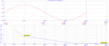
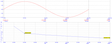
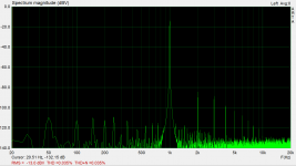
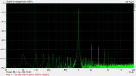
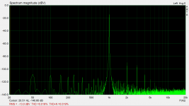
Ok, nice to know there is a interest in this kind of toplogy. This morning I did some distortion measurements for 10 Ohm load for now, 20V peak to peak.
01. bias 800mA
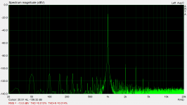
02. bias 875mA
03. bias 940mA
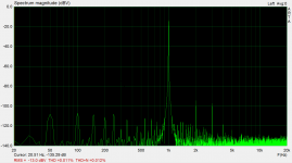
04. bias 1.05A
05. bias 1.11A
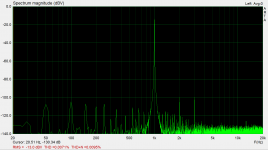
06. bias 1.27A
01. bias 800mA
02. bias 875mA
03. bias 940mA
04. bias 1.05A
05. bias 1.11A
06. bias 1.27A
Attachments

Good idea and nice asymmetric design, looking forward to see some real measurements
Can you tell what difference changing R208 makes?
And can you tell what changes you would suggest for 4 ohms load, and what power can be expected into 8 ohms and 4 ohms with one BJT and one MOSFET?
Hi, raising R208 value raises the output impedance or lowering dumping factor..
For mesasurements above it`s bypassed. Bass sounds tighter imo.
I think one output pair would be ok for about 25W amp with proper power supply and heatsinks.
- Home
- Amplifiers
- Solid State
- Single Ended CFA