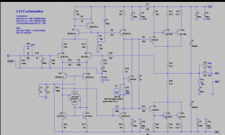
I want to build an integrated amplifier using famous power amplifiers L12-2 from China.
Instead of buying transformer, chassis, preamp etc. I decided to upgrade an existing amp a Grundig V8100 known also as Grundig V303. The amplifier has a heatsink big enough and transformer giving 2x41V DC to obtain 2x55 W for 8 ohm.
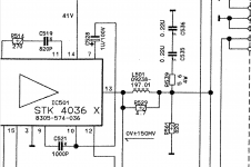
In power amp stage it uses STK4036X integrated circuits which are generally ok but whole device is designed for 220V AC. Actually, when using 230V AC in my country these ICs break down in many cases. So I want to disconnect them and put two L12-2s .
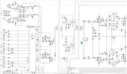
But initially I want to enable an equalizer connection and increase value of smoothing capacitors. I have noticed that in the back there are 2 sets of RCA sockets used for remote control outputs for dedicated tape recorder and CD. Since I’m not going to use neither of these devices these sockets can be useful for an equalizer. I want to plug it in between a connectors stage and preamplifier stage i.e. between plug P4A and socket P4L as on schematic below.
There I have a question to you because I see that preamplifier uses a potentiometer on initial stage ( sockets P41L and P5L) and than another potentiometer at the end ( see another picture) between sockets P5L and P8L which goes then to power amplifier. Why there is a 4 channel potentiometer being used in preamplifier stage ???
My another question relates to power supply. As you see below, after rectification current goes to main smoothing capacitors C653 and C562 having 6800uF/50V each. To them there are 2 resistors R565 and R564 connected in parallel. In my opinion in order to discharge capacitors when amplifier is not in use. But why these resistors are not equal ? One has 3.3K while another 10K.
Instead of buying transformer, chassis, preamp etc. I decided to upgrade an existing amp a Grundig V8100 known also as Grundig V303. The amplifier has a heatsink big enough and transformer giving 2x41V DC to obtain 2x55 W for 8 ohm.
In power amp stage it uses STK4036X integrated circuits which are generally ok but whole device is designed for 220V AC. Actually, when using 230V AC in my country these ICs break down in many cases. So I want to disconnect them and put two L12-2s .
But initially I want to enable an equalizer connection and increase value of smoothing capacitors. I have noticed that in the back there are 2 sets of RCA sockets used for remote control outputs for dedicated tape recorder and CD. Since I’m not going to use neither of these devices these sockets can be useful for an equalizer. I want to plug it in between a connectors stage and preamplifier stage i.e. between plug P4A and socket P4L as on schematic below.
There I have a question to you because I see that preamplifier uses a potentiometer on initial stage ( sockets P41L and P5L) and than another potentiometer at the end ( see another picture) between sockets P5L and P8L which goes then to power amplifier. Why there is a 4 channel potentiometer being used in preamplifier stage ???
My another question relates to power supply. As you see below, after rectification current goes to main smoothing capacitors C653 and C562 having 6800uF/50V each. To them there are 2 resistors R565 and R564 connected in parallel. In my opinion in order to discharge capacitors when amplifier is not in use. But why these resistors are not equal ? One has 3.3K while another 10K.
Attachments
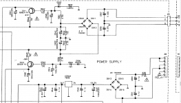
As far as the different values of bleeder resistors notice the lower value is in the negative power supply smoothing capacitor.
Briefly, the positive and negative half cycles are not equal ,parasitic effects will discharge a small amount during the negative cycle of the transformer,this gives a small variation in DC output .
The lower value in the negative supply means the timing of the discharge will be quicker,it also has other uses .
I would leave it as it is but if somebody has a different opinion ?
The larger the capacitor the slower the discharge rate so a smaller value of parallel resistor is required.
My point was that both sides of the power supply don't discharge evenly the negative side has a different timing that's why a smaller value of resistor is required .
This is about parallel discharge timing not a series resistor/capacitor timing.
My point was that both sides of the power supply don't discharge evenly the negative side has a different timing that's why a smaller value of resistor is required .
This is about parallel discharge timing not a series resistor/capacitor timing.
I have another question:
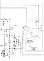
I want to get rid of STKs and put L12-2s instead. The signal out from L12-2 I want to connect to leg13 of former STK where it's signal was also going out.
The signal goes through coil L501, then between resistors R561 and R539 and then to speakers (up) and speaker protection (down).
That resistor R539 is big 5.6R and 4W (!) what I don't understand.
Maybe I should now connect the signal out after those resistors ?
Please help.
Attachments
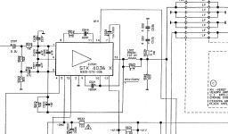
Its a Zobel network Peter so you need it to stop instability and back emf by the voice coil of the loudspeaker is stopped by the series coil and parallel resistor so disconnect pin 13 from the chip but connect your output from the new one to that point.
Have a look at -
Speaker Zobel / Impedance Equalization Network Circuit Calculator
Its a big wattage yes but I have seen burnt out lower wattage resistors ,its not really doing any harm .
I have built power amps without series inductance's just a series resistor but they are modifications of JLH designs who just used a resistance and are discrete not a big chip.
The power amplifier is connected to a power source (+, -, ground), output, input (signal ground) instead of the old one.
Clone power amplifiers L12-2 from China
https://aliexpress.ru/item/32809541289.html
Clone power amplifiers L12-2 from China
https://aliexpress.ru/item/32809541289.html
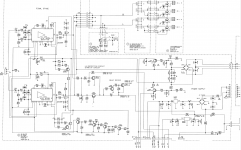
On a website L12-2 - modifcations - calvins-audio-pages I have found some modifications proposals whih are presented on schematic attached. I would like you to look on a right side with a Zobel network proposed consisting of coil L1 of 2,2 uH and resistor R35 of 2,2R. It is described as LR-network R35/L1 with values of 8-10Ohms for R35 and 1µH-2µH for L1.
In Grundig schematic (attached) there is also a LR network with a coil of unknown inductance and resistor 4,7 R which may also work I think.
But please have a look what is down from LR network on L12-2 schematic - there is resistor R21 10R/1W and capacitor C9 100n - they are both already on L12-2 plate (not modifications). In Grundig schematic there are (mentioned in previous post) resistors R539,R561 and capacitors C535 C536.
So I probably should desolder all of them ( leaving only L501/R529) as such branch (R21/C9) is already existing in L12-2
Attachments
If you are not replacing the integrated audio chip with another audio chip but a discrete amplifier circuit then yes you can do that.
Although the resistor at the output is parallel an inductance of 2.2uH I would check the inductance value of the wire-wound resistor as it could actually be enough to dispense with the inductance ,many of JLH,s amplifiers only had a wire-wound resistor at the output and I build amplifiers using the same method (after measuring the inductance value ) .
Although the resistor at the output is parallel an inductance of 2.2uH I would check the inductance value of the wire-wound resistor as it could actually be enough to dispense with the inductance ,many of JLH,s amplifiers only had a wire-wound resistor at the output and I build amplifiers using the same method (after measuring the inductance value ) .
Do you mean Grundig resistor R529 4.7R if it is wire-wounded ? I have no instrument to measure it's inductance.
Generally speaking I am going to desolder the STKs and desolder all resistors and capacitors "servicing" those ICs except that RL path (L1/R529) but I may do a bypass of that to check if there is any difference.
Generally speaking I am going to desolder the STKs and desolder all resistors and capacitors "servicing" those ICs except that RL path (L1/R529) but I may do a bypass of that to check if there is any difference.
It should have a powerful output helped by the cascode stage at the input upping the signal .
All amplifiers are judged on a personal basis one mans meat is another s poison, even "golden-ears " hi-fi reviewers can disagree.
" Near perfect " is detailed but with smoothness and above all "musicality " IE- makes your foot tap to the music, but that's just my opinion----see what I mean ?
All amplifiers are judged on a personal basis one mans meat is another s poison, even "golden-ears " hi-fi reviewers can disagree.
" Near perfect " is detailed but with smoothness and above all "musicality " IE- makes your foot tap to the music, but that's just my opinion----see what I mean ?
")
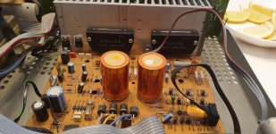
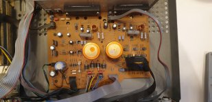
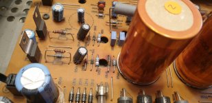
Project completed!
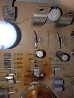
Now some pictures before and what was done to Grundig V8100/V303:
- rear connectors for remote control were changed to equalizer out and in sockets
- both STK 4036X were removed and so all semiconductors which were "supporting" them
- thanks to above semiconductors removal there was a place for adding additional 6800 uF capacitors
- I have left coils L501/502 and resistors R529/535 4R7 but changed them to 2W
- resistors discharging main capacitors R564/565 were changed to 2W and that R565 which causes problems in each amplifier was changed from 3,3K to 6,6 K
Attachments
- Home
- Amplifiers
- Solid State
- Grundig V8100/V303 upgrade with L12-2