Hello Everybody,
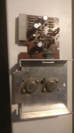
today I got a broken Technics SA-5250 Receiver. One Channel was dead. The Power Amplifiers are mounted on Cards, removing one Channel revealed the right channel to be dead. The Drivers and Power Transistors seems to be dead, Collector-Emitter-Short. The Supply Voltage is +-30V.
The Drivers are 2SC1567 and 2SA794. I'd like to substitute them with BD139/BD140, their Vce is lower, but I think 80V is still enough for +-30V.
The Power Transistors are 2SC1667 and 2SA837. For these I don't have a 100% fitting replacement, but I've found two pairs of really old looking 2SD551 and 2SB681, which should be fine, but I'm not quite sure about that. MJ21193/MJ21194 should be fitting too, but I'd have to order these ...
Maybe someone could verify my decision, so that I don't fry more transistors.
Thank you very much
Lukas
Your problem in using -BD139 is the much larger Hfe bias required to obtain the same gain--BF457 is a nearer match .
If you are "frying" BJT,s then check the heatsinks used and their connection to the power BJT,s , if the cards are detachable then how big is the heatsink on the card?
I notice there is a thermistor in the driver circuit ,is that functioning ?
4ohms is the lowest impedance recommended are your speakers rated lower?
Last edited:
Hi,
I'm sorry, but I'm unfamiliar with the term "Hfe Bias", I know Hfe and Biasing in an amplifier, but I'm unable to put these two together. In the working, Left Channel Module, the Drivers were already replaced once I think, there are BD139/BD140 put in, and it seems to work.
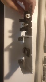
I haven't killed more Transistors, but I'd like to make sure, my replacements are okay, before I put them in and they die. The Thermistor is okay as far as I can check, I unsoldered it, put it on my multimeter and heated it up with my hot air gun, it changes its resistance. Just the TO-3 Output Devices are on a heatsink, even though the heatsink is seems kinda small to me. I'll upload a photo in a few minutes.
Regards
Lukas
PS: Forgive me for my englisch, it's definitely not the best, I hope you all can understand me")
EDIT: I added two pictures of the working channel.
I'm sorry, but I'm unfamiliar with the term "Hfe Bias", I know Hfe and Biasing in an amplifier, but I'm unable to put these two together. In the working, Left Channel Module, the Drivers were already replaced once I think, there are BD139/BD140 put in, and it seems to work.
I haven't killed more Transistors, but I'd like to make sure, my replacements are okay, before I put them in and they die. The Thermistor is okay as far as I can check, I unsoldered it, put it on my multimeter and heated it up with my hot air gun, it changes its resistance. Just the TO-3 Output Devices are on a heatsink, even though the heatsink is seems kinda small to me. I'll upload a photo in a few minutes.
Regards
Lukas
PS: Forgive me for my englisch, it's definitely not the best, I hope you all can understand me
EDIT: I added two pictures of the working channel.
Attachments
Last edited:
For a given bias current a certain amount of gain is achieved .
Manufacturers provide this data as a means of customers deciding which BJT to use in either a self designed amplifier or an already made one .
Simply put if you replace -2SC1567 with BD139 while it would work the actual gain would be lower .
BF457 is a recommended replacement but there are others but you need to check all the specifications not just the recommended voltage etc of the replacement.
The pin-outs match. The currently available “universal Jap TO-126 drivers” are the Fairchild C2960/A1220. Toshiba has a pair now, the TTC/A0004, but I’m not so certain they’re what they used to be. The BD’s will work - they have been used for drivers forever. Just use the -16 grade if you’re worried about gain.
Most any Jap TO-3 Complementary audio outputs will work at that low voltage. Heck, the 3055/2955 pair will work, if you put heat sinks on the drivers. A higher gain part would be better. The D551 is so old it’s not even in my Jap transistor manual from 1989 but would likely work. If you needed a modern replacement, I would use the 21193/4 - not because you need something that high power, but because they have higher gain than anything else you can get. Not spectacularly high, but up to about 8 amps will compete with most older Jap types except for the Sanken LAPTs (which they did make in TO-3s at one time). Toshiba made a couple super high speed TO-3 pairs,but they never saw much widespread use.
Most any Jap TO-3 Complementary audio outputs will work at that low voltage. Heck, the 3055/2955 pair will work, if you put heat sinks on the drivers. A higher gain part would be better. The D551 is so old it’s not even in my Jap transistor manual from 1989 but would likely work. If you needed a modern replacement, I would use the 21193/4 - not because you need something that high power, but because they have higher gain than anything else you can get. Not spectacularly high, but up to about 8 amps will compete with most older Jap types except for the Sanken LAPTs (which they did make in TO-3s at one time). Toshiba made a couple super high speed TO-3 pairs,but they never saw much widespread use.
Well then I'm going to put them in, I just need to get new insulation pads for the Output Transistors, the old ones broke when removing them.
Furthermore, I noticed, the protection relay won't work. TR702 seems to be broken too, the Relay doesn't have a flyback diode, so I'll find a replacement for this transistor and add this diode and try again.
Furthermore, I noticed, the protection relay won't work. TR702 seems to be broken too, the Relay doesn't have a flyback diode, so I'll find a replacement for this transistor and add this diode and try again.
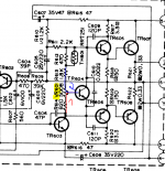
The Protection Circuitry works now and I've replaced the failed Parts on the main amp pcb. Now, before powering, I would like to set the bias current as low as possible, but I'm not quite sure, which way to turn the potentiometer. I've attached a picture to clarify. I think it should be turned all the way to the left, so that R614 to the Base of the VBE multiplier is 500 Ohms (Variant 1). The Second option is Variant 2, R613 to the base would be 500 Ohms.
Maybe someone with more knowledge and experience could just verify this for me before I turn it on ...!
Regards
Lukas
Maybe someone with more knowledge and experience could just verify this for me before I turn it on ...!
Regards
Lukas
Attachments
Lukas!
The top position in the diagram corresponds to a lower current. Check trim tab contact. To clear. Rotate slowly, controlling current (10-30 mA) or bias on the 0.33 resistor (5-10 mV). Check after warming up. Turn on the Edison 220-volt lamp 40 watts in series in the primary electrical circuit))).
The top position in the diagram corresponds to a lower current. Check trim tab contact. To clear. Rotate slowly, controlling current (10-30 mA) or bias on the 0.33 resistor (5-10 mV). Check after warming up. Turn on the Edison 220-volt lamp 40 watts in series in the primary electrical circuit))).
Now when I'm looking at it again, it's very clear, it was late yesterday
I turned the pot all the way up, just like you described and turned the amp on.
For a brief moment, I was able to read 10mV drop across the Emitter Resistors on my DMM, but then the protection relay kicks in and shuts the whole thing of. There seems to be some kind of DC at the output. I checked all resistors on the board, they are okay, all transistors are okay too, as far as I can check with my simple multimeter.
With the original working card, everything works plugged into both channels, so it's not the protections fault. Has anyone another idea, what to test?
Regards
Lukas
Check all the connected transistors 601-607 (breakdown, breakage) insulation from the radiator (mica, washers), electrolytic capacitors (leakage, breakdown), resistors (breakage), solders (jumpers).
Visually and using a multimeter, compare both channels by resistances and diodes (junctions BJT) with the power off.
In some cases, non-emergency switching without output transistors (without load) is possible - it is not guaranteed (((
Visually and using a multimeter, compare both channels by resistances and diodes (junctions BJT) with the power off.
In some cases, non-emergency switching without output transistors (without load) is possible - it is not guaranteed (((
Sucess!
It turns out, someone tampered with the device before I got it already. The input stages 2SA666A were replaced to BC560, without taking care of the pinout! I put a pair of KSA1015's in, and it works! I set the Bias according to the service manual to 6mV, I'll check again in half an hour.
Would it make sense to change the transistors on the working card for both channels being identically or is it "never touch a running power amplifier"?
I'm quite happy right now!
Lukas
I wasn't going to, but now it seems like I have to do - the earlier working card makes problems now. It has a very "dull" sound, high tones aren't amplified really much. Bias Current is identical to the other card and corresponds with the service manual - 5-6mV.
I'll do the same procedure, check all Transistors, Resistors and Caps and will have a look at it after that
EDIT: I replaced the Bias-Pot, that was kind of dodgy, now the amplifier seems to be clipping, I'll hook up a scope in a few minutes.
I'll do the same procedure, check all Transistors, Resistors and Caps and will have a look at it after that
EDIT: I replaced the Bias-Pot, that was kind of dodgy, now the amplifier seems to be clipping, I'll hook up a scope in a few minutes.
Last edited:
Lukas,
Just to offer some perspective, I am currently using as a daily driver a Sony TA-3200F amp (great sounder) which, it just so happens, has pretty distinctly different parts in the input circuitry (focus on active parts). One channel was almost completely rebuilt, the other maintains almost all original parts. In measurements, the "overhauled" channel shows less distortion - 0.0086% vs. 0.013% THD - but I'd caution physical specifics (such as relative location of channel's circuitry in the enclosure - such as vs. power supply - etc.) may have just as much an influence over such low measurements as the new vs old transistors.
- Can I hear a difference? Not even a trace to my ears (didn't spend much time on it either).
- Will I spend the time later to make the channels symmetrical? Without a doubt.
- Am I happy for now with the amp in this non-symmetric configuration? Definitely.
I wouldnt have changed the second channel, if it hadn't died
I'm one step closer now, R617, 3.3 Ohms, measures 11 Megaohms, I replaced it with a new resistor.
The new problem seems to be a much, much to high bias current, the voltage drop is more than 500mV on my analog Meter, I turned it on and in less than a second off again...
I'll continue checking the resistors around the Vbe Multiplier, and maybe replace the Vbe Multiplier Transistor.
I got another step further. The broken card seems to have too much gain and clips very early.
The broken Card already clips at .2V RMS with a 1k Sine and sound very distorted all in all, the high frequencies aren't amplified really good, it's a heavy low end. The working card clips at .9V RMS with the 1k sine. Both are measured with an 8 Ohm Resistor at the output.
Any ideas ...?
I begin to hate this amp again ...
Sounds like an open feedback resistor at the very least. It happens.The broken card seems to have too much gain and clips very early.
- Status
- This old topic is closed. If you want to reopen this topic, contact a moderator using the "Report Post" button.
- Home
- Amplifiers
- Solid State
- Technics SA-5250 Transistor Replacement