Hello everyone.
I'm trying to fix my old Sansui AU-117 (first edition) since the left channel is nearly dead on the output (very low volume noisy distorted sound).
The headphones work as they should on both channels and the right channel sounds good on the output speakers.
I replaced all the electrolytic capacitors, but still the same problem. The driver transistors have no problem as far as I'm concerned since there is good sound from the headphones.
The BIAS settings should be 20mA and 13mV. I tested the right channel and the readings were correct but when I tried to check the left the readings were far off and the pot was not adjusting the voltage level more than 0.5mV. And I left the bias pot to a certain voltage and current setting I can't guess (since the obvious problem was around the output transistor).
So I decided to test and replace the output transistors for the left channel.
There are two main output transistors per channel (plus 2 smaller ones I would replace if the first replacement didn't work well)
1 x 2SD313 and 1 x 2SB507.
I took all of them off and I measured them and everything seemed good for both channels' transistors, but since they are more than 40 years old I decided to change the left channel ones.
Impossible to find these transistors near me I bough 1 x TIP41C for the 2SD313 and 1 x TIP42C for the SB507.
After I replaced the 2SD313, I powered the amp but it immediately blew the fuse (it hadn't happened before, after 3 days of testing). I decided to change the bias pot setting even if it's impossible to make any measurement since the amp blew a fuse (by just putting the screw marker at the same point where the right channel's one is).
I replaced the fuse and powered it on but it blew the new fuse again. I replaced the new transistor with the old one (I thought that, even if it may be damaged, it didn't blew fuses and it would help me to see the current BIAS readings to adjust them). I changed the fuse and powered the amp, but it once again blew the fuse.
So after a couple of more blown fuses I decided to check the power rectifier diodes. They are of IR10D type (something like 200V, 1A) and I found one out of six being bad. No reading on both sides. Since I have some spare 1N4003 I 'm thinking about replacing the IR10D with one (they also are 200V, 1A), but I'm not sure if they are the correct type for the job.
So what do you think about the situation? Any advice? Where the problem could be? Are these N4003 diodes ok for the job (replacing just one and leave the rest IR10D).
Sorry for the long message. Hope I didn't confuse you and thanks in advance for the interest.
Different transistors will have different Vbe values, meaning the bias point will be different on the pot, or even that the bias pot range will not cover the correct range.
You should always wind the pot to the minimum bias end of travel after changing transistors or you will risk overbias and fuse-blowing.
Your problem is perhaps the bias transistor, not the output transistors.
The bias pot itself might be failing. Basically suspect the bias circuit itself, and I would have taken lots of voltage readings from both good and bad channel before replacing those transistors and noted them down and found where the differences were.
Dim bulb tester is also wise precaution, as is adding series resistance between PSU and amp board (to limit current).
Thanks Mark for the reply. I know I should do more, but now the situation is like that and I 'm trying to find a solution. I checked all the transistors off board the measurements were more or less similar, but old transistors can fail and according to certain techs the ones I tried are direct replacements.
The real problem is I touched the bias pot before I replace the transistor and now I'm trapped in this situation.
The real problem is I touched the bias pot before I replace the transistor and now I'm trapped in this situation.
if a rectifier diode is bad i would change it.............yes, a 1n4003 could fit.
measure the bias setting transistor, the driver transistors and the (emitter)resistors at the output transistors
........(you can compare the values of the bad channel
with the good channel........)
measure the bias setting transistor, the driver transistors and the (emitter)resistors at the output transistors
........(you can compare the values of the bad channel
with the good channel........)
You know the bias voltage can be measured without the output devices in circuit? So its easy to figure out the minimum bias direction for the bias pot (it ought to be fully CCW if the unit's been well designed).
The Vbe's would have to be similar within a few millivolts to not radically change the bias... Even the exact replaces require rebiasing.I checked all the transistors off board the measurements were more or less similar, but old transistors can fail and according to certain techs the ones I tried are direct replacements.
You know the bias voltage can be measured without the output devices in circuit? So its easy to figure out the minimum bias direction for the bias pot (it ought to be fully CCW if the unit's been well designed).
The Vbe's would have to be similar within a few millivolts to not radically change the bias... Even the exact replaces require rebiasing.
Do I need to place any resistors in place of the transistors and should I remove both channel transistors? I will have the volume pot at zero - if the amp switch on.
Actually I took the pot out and I measured it. Everything works well. It's 470ohms (even if my max readings show 520ohms). I think I should start from the maximum resistance setting. Is this correct?
I feel a bit lucky today.
I replaced the fuse and the amp powers up properly. I measured around the transistor bias and the minimum setting is CW.
The short was caused because I hadn't insulated the transistor screw. Nothing to do with overbias or incompatible transistor pair.
.
Nothing is burned. The sound comes good out of the headphones on both channels.
The right channel sounds good on the speaker and it can be biased but the left channel sounds low and distorted and its bias pot can't affect and shows no real measurements (less than 1mV.)
But I've made a discovery. When I shut down the amp the speaker sounds good while it fades.
Does it mean that I have a capacitor issue (but I replaced all the big electrolytic ones)? Which capacitors? Any other idea?
Dim bulb tester is also wise precaution, as is adding series resistance between PSU and amp board (to limit current).
Its best and easier to add the MBT on the mains line
Powering Your Radio Safely with a Dim-bulb Tester
Sounds like a fault to me, and probably not a cap.
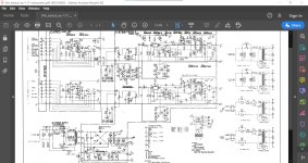
What voltage do you achieve across TR07 (vbe multiplier) when the bias pre-set is set for maximum bias? You should be able to get to at least 2.5 volts across that transistor at which point the output stage should start drawing current.
What voltage do you achieve across TR07 (vbe multiplier) when the bias pre-set is set for maximum bias? You should be able to get to at least 2.5 volts across that transistor at which point the output stage should start drawing current.
Thanks for the suggestion Mooly. I guess there is a fault anyways since the channel doesn't work.
I measure across (Base - Emmiter) transistor 7 around 700mV. The Bias pot doesn't affect it.
The same number is given by transistor 8. And its bias pot also doesn't affect it. But the channel works great.
Do I do something wrong?
I measure across (Base - Emmiter) transistor 7 around 700mV. The Bias pot doesn't affect it.
The same number is given by transistor 8. And its bias pot also doesn't affect it. But the channel works great.
Do I do something wrong?
Its the collector - emitter voltage you want. You need to overcome the four forward volt drops of the driver and output transistors which will be around 0.6v each. So that means you need to see a voltage of around 2.4 volts across TR07 C and E.
Thanks again. Without touching the bias pot, and while it is below half way, it shows around 1.7v, so Ι guess it can easily go up to 2.something.
What I realise while I'm checking through my oscilloscope is that the problem starts just after IC1 (that's where there is difference in the waveform comparing to the other channel). But I doubt it that it's something with the IC since the sound is good through the headphones . And the big caps next to it are replaced. So I have to move further down the path.
Hmmm.
The diagram I'm looking at is (I'm pretty sure) for the original AU117 and it's a classic all discrete amp. No IC's in sight...
So what am I looking at and what have you got in front of you?
They call the first transistor IC1 (it's a double transistor- I've already written it)
Ah, OK. I was thinking you meant an IC somewhere.
So you need to concentrate on the bias problem and I would advise the use of a bulb tester while working on this.
Detail is critical to diagnosing this.
Are you certain that all the low value resistors in the output stage are good? That includes both 0.33 ohm's, both 220 ohm's and both 6.8 ohm's.
Check that R33 and R35 are both good. Check them out of circuit.
When the amp is on, is the DC offset correct (no DC voltage at the speaker terminals)?
If you can not find anything wrong by inspection then you have to turn the pre-set to see what the adjustment range is. The no bias problem is a way into finding the fault.
Ah, OK. I was thinking you meant an IC somewhere.
So you need to concentrate on the bias problem and I would advise the use of a bulb tester while working on this.
Detail is critical to diagnosing this.
Are you certain that all the low value resistors in the output stage are good? That includes both 0.33 ohm's, both 220 ohm's and both 6.8 ohm's.
Check that R33 and R35 are both good. Check them out of circuit.
When the amp is on, is the DC offset correct (no DC voltage at the speaker terminals)?
If you can not find anything wrong by inspection then you have to turn the pre-set to see what the adjustment range is. The no bias problem is a way into finding the fault.
Thanks for the advice and help. I will make a dim bulb tester. Unfortunatelly an accident happen, my hand slipped while i was measuring one of the output transistors of the right channel, and now all the sound is faint from the good channel.
I placed the known good transistors on it and I put the old transistors on the other channel. I measured all around the transistors and all my voltages are good, but still there is no sound. What may have happened???
On the other hand with the bad transistors the channel plays good on the headphones and while I was measuring I realised that the bias pot doesn't work at all as a resistor (even if when I removed it it was working properly).
- Status
- This old topic is closed. If you want to reopen this topic, contact a moderator using the "Report Post" button.
- Home
- Amplifiers
- Solid State
- Sansui amp keeps blowing fuses after output transistor replacement.