En:
Hello forum friends! all right?
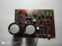
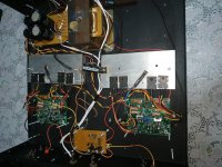
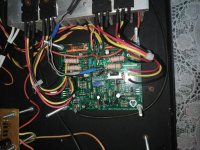
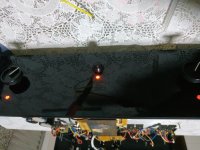
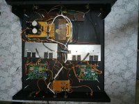
This is my fist topic here on the forum so I ask you to have a little patience with me. I wanted your help with this amplifier that I won. Researching a little about discovering that it is an amplifier a little difficult to find, but it does not mean that it is of quality.. I liked the sound it produces, it's very sharp, shiny and very strong on the bass.. (I used a pair of 95 db sensitivity speakers each, and that helps a lot.) I did a type of reverse engineering to try to understand his circuit, but in the simulator it does not work right way. I would like the opinion of you friends. What you think of the circuit? Whats wrong? Is it possible to improve?
Attached is a PCB image of the circuit in PDF and * .ms14 (Multisim 14)
** About the amplifier and the creator of this circuit:
This circuit is by a Brazilian engineer known as "Sossego" (in English it would be quiet), in which few units of the same amplifier were produced. I believe that this amplifier, the P800 has a maximum power of 100w at 8 ohms or 130w at 4 ohms.
PT:
Olá amigos do fórum! Tudo certo?
Este é o meu primeiro tópico aqui no fórum, então peço que você tenha um pouco de paciência comigo. Queria sua ajuda com este amplificador que ganhei. Pesquisando um pouco sobre descobrir que é um amplificador um pouco difícil de encontrar, mas isso não significa que seja de qualidade .. Gostei do som que produz, é muito nítido, brilhante e muito forte no baixo .. (I usei um par de alto-falantes de sensibilidade de 95 db cada, e isso ajuda bastante.) Fiz um tipo de engenharia reversa para tentar entender o circuito dele, mas no simulador não funciona da maneira certa. Eu gostaria da opinião de vocês amigos. O que você acha do circuito? O que está errado? É possível melhorar?
Em anexo está uma imagem PCB do circuito em PDF e * .ms14 (Multisim 14)
** Sobre o amplificador e o criador deste circuito:
Este circuito é de um engenheiro brasileiro conhecido como "Sossego" (em inglês, seria silencioso), no qual foram produzidas poucas unidades do mesmo amplificador. Eu acredito que este amplificador, o P800 tem uma potência máxima de 100w a 8 ohms ou 130w a 4 ohms.
Hello forum friends! all right?
This is my fist topic here on the forum so I ask you to have a little patience with me. I wanted your help with this amplifier that I won. Researching a little about discovering that it is an amplifier a little difficult to find, but it does not mean that it is of quality.. I liked the sound it produces, it's very sharp, shiny and very strong on the bass.. (I used a pair of 95 db sensitivity speakers each, and that helps a lot.) I did a type of reverse engineering to try to understand his circuit, but in the simulator it does not work right way. I would like the opinion of you friends. What you think of the circuit? Whats wrong? Is it possible to improve?
Attached is a PCB image of the circuit in PDF and * .ms14 (Multisim 14)
** About the amplifier and the creator of this circuit:
This circuit is by a Brazilian engineer known as "Sossego" (in English it would be quiet), in which few units of the same amplifier were produced. I believe that this amplifier, the P800 has a maximum power of 100w at 8 ohms or 130w at 4 ohms.
PT:
Olá amigos do fórum! Tudo certo?
Este é o meu primeiro tópico aqui no fórum, então peço que você tenha um pouco de paciência comigo. Queria sua ajuda com este amplificador que ganhei. Pesquisando um pouco sobre descobrir que é um amplificador um pouco difícil de encontrar, mas isso não significa que seja de qualidade .. Gostei do som que produz, é muito nítido, brilhante e muito forte no baixo .. (I usei um par de alto-falantes de sensibilidade de 95 db cada, e isso ajuda bastante.) Fiz um tipo de engenharia reversa para tentar entender o circuito dele, mas no simulador não funciona da maneira certa. Eu gostaria da opinião de vocês amigos. O que você acha do circuito? O que está errado? É possível melhorar?
Em anexo está uma imagem PCB do circuito em PDF e * .ms14 (Multisim 14)
** Sobre o amplificador e o criador deste circuito:
Este circuito é de um engenheiro brasileiro conhecido como "Sossego" (em inglês, seria silencioso), no qual foram produzidas poucas unidades do mesmo amplificador. Eu acredito que este amplificador, o P800 tem uma potência máxima de 100w a 8 ohms ou 130w a 4 ohms.
Attachments
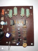
Its certainly not a standard type of power amp circuit , you have plenty of feedback and more than one type of feedback which should make it pretty stable but I do not like the 1970,s type components .
You would be doing yourself a favor by updating them especially those rusty wirewound types as in that state they start to go high resistance under load due to the cup ends losing full contact with the resistance wire .
If I had it I would replace all the resistors with low noise metal film ones and I never like those orange capacitors while they functioned they should not be used in good quality audio.
Its not a big job up-rating it as there is not a lot of components and up-rate the BC547,s to BC550C .
You like a "sharp sound " ? I take it this is a translation problem where you mean "detailed " but it should not be wearing with over -the -top excitement , better to have detail and smoothness.
But those old parts are not doing it any favors .
Work with the basic circuit as its different from most but do something about the parts including changing that 22pf capacitor for a good quality polystyrene one and change the 100mfd frequency response adjustment capacitor for a good quality modern one .
Its certainly not a standard type of power amp circuit , you have plenty of feedback and more than one type of feedback which should make it pretty stable but I do not like the 1970,s type components .
You would be doing yourself a favor by updating them especially those rusty wirewound types as in that state they start to go high resistance under load due to the cup ends losing full contact with the resistance wire .
If I had it I would replace all the resistors with low noise metal film ones and I never like those orange capacitors while they functioned they should not be used in good quality audio.
Its not a big job up-rating it as there is not a lot of components and up-rate the BC547,s to BC550C .
You like a "sharp sound " ? I take it this is a translation problem where you mean "detailed " but it should not be wearing with over -the -top excitement , better to have detail and smoothness.
But those old parts are not doing it any favors .
Work with the basic circuit as its different from most but do something about the parts including changing that 22pf capacitor for a good quality polystyrene one and change the 100mfd frequency response adjustment capacitor for a good quality modern one .
Yes duncan2, I meant that he responds well, he is linear, he responds well to highs, it doesn't seem to be very sharp, but something clean and sharp. Translation does not aid in accurate understanding.
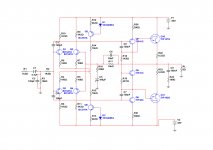
rayma said:You are missing the parts that feeds the Zener diodes. Perhaps resistors from the other supply rail.
I would replace all the passive parts. Are you certain of the value of R24? The usual value is 10R.
Rayman, I'm sure it's 100R, I confess I was surprised when I saw 100R on the R24
MKT capacitors are polyester. I've replaced paper with MKT and did not like the sound. Polyprophylene MKP is more respected, at least by John Curl.
The repair shop owner in Piros said he had a lot more blown outputs in darlington output amps than in the ones that had drivers on a separate heat sink. This amp has darlington output transistors.
I wouldn't replace every resistor, unnecessary repairs can lift lands off old boards. Maybe leave them alone unless the humidity has caused the values to wander. Allen Bradley & Sprague carbon comp post 1961 were pretty stable; other brands did not have the mil spec paint to keep water out. These are definitely not AB or Sprague.
I used TIP41c/42c as drivers in an AX6 and thought the highs were lacking, as compared to an original 1970 board with 40409/40410 drivers (no longer available). I tried MJE15028/29 and the result was a lot better. Ft 3 mhz versus 30 mhz may be the difference. If your source tracks are house, techno, or similar, there may not be enough high frequency content to be audibly different.
Seems a bit over complicated, and with 120 pf b-e on the drivers, slew rate may not be anything to brag about either. In single pair output transistor amps for +-45 v there are many apex designs with a lot fewer parts. Ones with regular BJT output transistors, not darlingtons.
Happy modification.
Last edited:
Stability has a lot to do with layout. Cross coupling between lands of input (base) and output (collectors). You can get some idea of what you can get away with using Spice simulator, but it doesn't model the layout. So try some things. My ST120 PC14 has 51 pf between b & c just as your system does the 120's. Maybe 51 would work. Definitely look with scope or analog voltmeter with 390 pf series cap series negative lead on 10 VAC scale for oscillation. After mods.What capacitance do you suggest for drivers?
")
There can also be sticking to the voltage rail on clipping problems, you should test for that.
The feedback to q2 & q4 is a particularly sensitive point for that can cause oscillation.
Last edited:
Rather than wander off into design which I don't do, I suggest you take your transformer filter caps & heatsinks and build an AX14 80 w A Directory of Apex Audio Amplifiers
You don't have to use those exotic drivers and outputs Mike Slavkovik always specifies, he lives in Europe. I built an AX6 which fits my transformer, I used MJE15028/29 as drivers. After the disappointing TIP41c/42c experiment. For output transistors, depends on how your heat sinks are drilled & what's in stock. TO3 pattern, MJ15003/15004, or MJ802/4502, or more expensive MJ15024/25 or MJ15193/15194. If you have single hole pattern drilled heat sink, 2SA1943/2SC5200 or MJL21193/194 or MJL4281/4502 or MJW3281/1302 or whatever the distributor has in genuine parts. On tends to make interchangeable MJL/NJL/MJW/NJW parts I don't see much difference but look at the datasheets the day you buy, On flogs off rejects with 250 mw power rating or 50 v Vceo rating that way some times.
Those precious BC547/557 inputs I tend to use MPS8099/8599 or MPSA06/56. Same for 2n5401. Instead of $35 a hundred I got the MPS/MPSA for $8 a hundred, and they had super gain (~300) and were quiet. The MJE340 and bd139 you might be able to get, but I used TO220 package 30 mhz ft parts for VAS in my AX6 without dire results.
then you have something you know will work, and if you have access to a circuit board etch house, there are gerber files too.
One trick for reliability, I put little heat sinks on drivers & VAS, even though not "required". I saw them out of window screen frames, then drill. I do use heat sink compound, one tube has lasted me 40 years.
Have fun.
Last edited:
I really liked the idea and the AX14 amplifier. Until then, I have some project amplifiers from Brazil, but my main MX50 amplifier (DIY Chines), which has a sound that I really like. I will show here in this topic the evolution of the amplifier over time. I believe that in 1 month I will have the amplifier ready to show. I need to renew his case, because it is in bad condition and I will show the before and after. I look forward to starting making the PCB.
Q7 Q8 are reversed; also flipped.
(And Rayma's Zener-feeders.)
R24 is more likely 10 Ohms (but 100 is not impossible).
It's not an unusual circuit.
De fato, as DICA estão corretas, mas as BC557 e 547 estão invertidas. Quanto à potência do diodo zener, essa e a conexão que está na placa fornecem + -800 mVDC para os BCs. Vou postar uma nova foto do diagrama.
Q7 Q8 are reversed; also flipped.
(And Rayma's Zener-feeders.)
R24 is more likely 10 Ohms (but 100 is not impossible).
It's not an unusual circuit.
#REPOST
In fact, the TIPs are correct, but the BC557 and 547 are reversed. As for the power of the zener diode, this and the connection on the board provide + -800 mVDC for the BCs. I will post a new photo of the diagram.
Hello friends, I made an "AX-14 Golosa" with two pairs of output transistors, but, I don't know why it doesn't work properly. The only replacement I made was on the output transistors that I put a pair of 2SA1693 AND 2SC4466 instead of the 2SA1943 and 2SC5200, and in the bias I replaced the BD139 with MJE340. I can't adjust the bias and at the exit I have a noise similar to a siren. My current source provides + -25VDC. I wanted to know if the cause is MJE340 from bias or if there is something else I missed.
Thanks.
Thanks.
Why did you replace BD139 with a MJE340 ?
It isn't the correct replacement they have different gains at different currents for a start, your bias is set for the BD139 BJT no wonder you cant adjust the bias.
Different current required also for the output devices .
If you haven't changed the passive components to suite then its not surprising you have problems .
Why did you replace BD139 with a MJE340 ?
It isn't the correct replacement they have different gains at different currents for a start, your bias is set for the BD139 BJT no wonder you cant adjust the bias.
Different current required also for the output devices .
If you haven't changed the passive components to suite then its not surprising you have problems .
I replaced the MJE340 with a BD139 and the same thing occurred to me.
Because we don't live in Europe and telefunken & Phillips originals are not available. the imitation bd139 we get from NTE & fairchild have a lot of the specs left off of the unicorn like originals (outside FDR).Why did you replace BD139 with a MJE340 ?
The siren noise is oscillation, probably flat topped. Likely a wiring error if you did not use original artwork from APEX. I was taught a nearly foolproof method to "buzz" a new circuit, at work. Take the schematic, turn into wire lists. Every point has a unique name. Every net of connections is one entry, with a listing for every component point name. Then buzz the pcb to the lists, using the ohms (diode) scale beeper. Mark terminations off the list with a highlighter pencil as you go. If there are more leads in a net than in the list, one of them is an error. If there are less leads in a net than in the list, one is missing.
Then, about the incorrect output transistor idle current. Just using a different brand of 2SA1943/2SC5200 output transistors will throw Mike S. plan for the vbe multiplier off. And you used some other set of output transistors altogether. Not tragic, just life, you have to cope with real parts, not some ideal set of parts from some mythical European perfection parts supply.
Measure the voltage between the two driver bases. Should be something between 1.4 and 3 v. If not, you have some sort of wiring error.
If so, and OT idle current is on the low side, then fiddle with the resistors around the vbe multiplier to find something that works. Hint- if you replace a resistor with one too high in value, (too much idle current), then you can later parallel it with another resistor to lower the value. Just bend hooks on the parallel resistor and solder it on top of the old one that has too high a value. Whereas if you go to low with a replacement resistor experiment, then the only option to incorrect result is to remove and replace it. Too many removals on PCB lands pull them off the board and cause them to be damaged.
I can't tell you which resistor around the vbe multiplier to change, all the amps I work on have diode stacks for idle bias collapse with heat instead of vbe multiplier transistors.
Build your skills & have fun.
Last edited:
Sounds like the "Royal WE " Indianajo so does Alisson live in the US of A ?
Fairchild selling BD fakes ?? hard to believe as I always looked up to that American company--how the mighty have fallen !
Luckily I have a large collection of original active devices from Mullard /Ferranti etc not one is a fake but I take your word on what is now taking place in industry ( that's if any of it is left in the Western World ).
She could do with an oscilloscope .
Fairchild acquired by ON in 2015- Fortune 1000 company I get the motivation still sub standard active devices from a $ Billion company ?
No Ft spec on any fairchild BD139 spec sheet I have seen. Ft 190 mhz on the phillips datasheet I downloaded. People line up to buy these from fairchild. Not me. Could be a pn2222 die in a heat sink package with fatter bond wires for all I can tell.Indianajo so does Alisson live in the US of A ?
Fairchild selling BD fakes ?? hard to believe as I always looked up to that American company--how the mighty have fallen !
Luckily I have a large collection of original active devices from Mullard /Ferranti etc not one is a fake but I take your word on what is now taking place in industry ( that's if any of it is left in the Western World ).
Fairchild acquired by ON in 2015- Fortune 1000 company I get the motivation still sub standard active devices from a $ Billion company ?
I had the impression that the OP lived in Brazil or some other mercosur country.
NTE makes tons of money selling replacement transistors with all the specs left off. The part name matches. Sometimes they work. who cares if you can't hear the cymbals or top octave piano? I do. I still have 14 khz ears. I thought TIP31c/32c with 3 mhz ft should be fine for hifi. WONG! MJE15028/29 with 30 mhz ft is doing the job now; sounds just like unobtanium RCA 40409/40410 drivers.
Last edited:
Completion of the amplifier
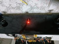
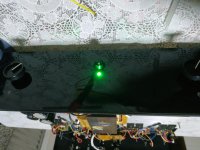
Hello friends! all right? After a long time I return here with the amplifier finished, without noise, oscillations or any other type of problems. The assembly was completely handmade, but without any problem. I used JLCPCB to manufacture the AX14 boards with the PRASI design. I reused the old Palmer clipping indicator plate to build my favorite clipping circuit. I am currently using a transformer from an old Pionner SX 303R that provides 63VDC, and I am using 8 Ohm speakers with a sensitivity of 95db / 1w that support a maximum of 120 Watts, I have 107 Watts before the signal indicate clipping. My next project for this amplifier, is to marry it with a good pre-amplifier, since my sources can't easily excite and I end up with low volume. I would like to know from friends which pre-amplifier the friends recommend for the wedding to be perfect between the sources and the amplifier?
I thank everyone who helped me so far.
P.S: It would be great if the preamp used OP-AMP, as I have a lot of NE5532, OPA2134 and TL072. I usually like the NE5532 and OPA2134 very much.About the problem I was having earlier was caused by an error of mine, in which I put 4K7 resistors in place of 4R7.
Attachments
Last edited:
- Status
- This old topic is closed. If you want to reopen this topic, contact a moderator using the "Report Post" button.
- Home
- Amplifiers
- Solid State
- Old power amplifier from Brazil "Palmer P800"