Solid State Relay - SSR
I tried to find ready made SSR on web but not mach choice there so I designed my own one.
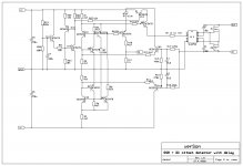
Here is SSR with quite new MOSFET driver Si8752.
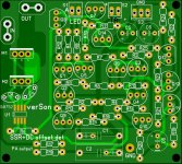
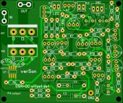
I did two versions with TO220 mosfets and TO247 mosfets.
It includes DC offset detection and turn on delay.
Attached schematic and PCB layouts, if anybody interested to buy the PCB let me know.
Damir
Correct schematic is here: https://www.diyaudio.com/forums/solid-state/355093-ssr-power-amps.html#post6219435
I tried to find ready made SSR on web but not mach choice there so I designed my own one.
Here is SSR with quite new MOSFET driver Si8752.
I did two versions with TO220 mosfets and TO247 mosfets.
It includes DC offset detection and turn on delay.
Attached schematic and PCB layouts, if anybody interested to buy the PCB let me know.
Damir
Correct schematic is here: https://www.diyaudio.com/forums/solid-state/355093-ssr-power-amps.html#post6219435
Attachments

Last edited:
14 transistors is fair old number, even with the delay - does it detect single rail failure too?
Your schematic has an error (not in the PCB layout) - the MOSFET sources should be commoned.
[ BTW I had a go at designed a circuit for this, no delay, but rail-failure and DC-offset detection:

Its based on Doug Self's protect circuit but with opto isolators instead of relays and biasing from the rails.
Your schematic has an error (not in the PCB layout) - the MOSFET sources should be commoned.
[ BTW I had a go at designed a circuit for this, no delay, but rail-failure and DC-offset detection:
Its based on Doug Self's protect circuit but with opto isolators instead of relays and biasing from the rails.
It looks like you have M2 drawn backwards on your schematic.
S and D should be flipped.
Yes, you are correct, but PCB is OK.

14 transistors is fair old number, even with the delay - does it detect single rail failure too?
Your schematic has an error (not in the PCB layout) - the MOSFET sources should be commoned.
Its based on Doug Self's protect circuit but with opto isolators instead of relays and biasing from the rails.
Transistors are cheap, why to count how many.
Single rail failure will produce DC offset at the output and it will trigger it and disconnect loudspeaker very quickly in less then 35 usec.
There is delay of about 3 sec (Q11, Q12, Q13, Q14) on turn on to prevent tamp (in same power amps).
Last edited:
Looks good - which would be preferred for +/-55Vdc - +/-66Vdc? Might be obvious, but this can be driven directly from Amp rails?
Are you planning a GB, or just selling individually?
It needs external power supply from +-12V to +-20V.
Hi.
I like your pcb, what's the size, i might want a couple,
One for TO220 mosfets 70mm x 63mm, and the one for TO247 mosfets 75mm x 63mm, two layers, 2oz copper.
28 transistors for stereo amp probably out-numbers the rest of the amp though (!), and each is a potential point of failure - protection circuits ought to be as simple and robust as possible I reckon, lest more issues are created than solved.Transistors are cheap, why to count how many.
Ah yes, that's true. I quite like the way the Doug Self circuit gates the relay/SSR on both rails having a minimum voltage, as this will catch transients at startup and also deal with asymmetric rail-decay on switch off. All with 5 transistors for both channels, though adding a delay circuit would increase that number a bit.Single rail failure will produce DC offset at the output and it will trigger it and disconnect loudspeaker very quickly in less then 35 usec.
I get the feeling you have a big stock of transistorsThere is delay of about 3 sec (Q11, Q12, Q13, Q14) on turn on to prevent tamp (in same power amps).
28 transistors for stereo amp probably out-numbers the rest of the amp though (!), and each is a potential point of failure - protection circuits ought to be as simple and robust as possible I reckon, lest more issues are created than solved.
Ah yes, that's true. I quite like the way the Doug Self circuit gates the relay/SSR on both rails having a minimum voltage, as this will catch transients at startup and also deal with asymmetric rail-decay on switch off. All with 5 transistors for both channels, though adding a delay circuit would increase that number a bit.
I get the feeling you have a big stock of transistors
28 transistors and 2 mosfet drivers.
This is DIY, hobby, if one has to solder just few transistors job is finished to soon, what satisfaction in that?And no, I don't sell transistors.
Hi Damir,
A few questons:
+ Where does this SSR get inserted?
- Before the FB point
- After the FB point, before the output inductor
- After the output inductor
+ What is the RDS_ON of the switch?
+ Have you measured how much distortion this SSR adds?
The RDS_ON of SSRs is very non linear, so I am wondering what is the impact on distortion.
Best, Sandro
Hi Damir,
A few questons:
+ Where does this SSR get inserted?
- Before the FB point
- After the FB point, before the output inductor
- After the output inductor
+ What is the RDS_ON of the switch?
+ Have you measured how much distortion this SSR adds?
The RDS_ON of SSRs is very non linear, so I am wondering what is the impact on distortion.
Btioest, Sandro
Hi Sandro,
SSR to be connected just between amp output and output connector.
I used Toshiba MOSFET TK72E12N1 with RDS_ON 3.6 mohm and I don't see it as non linear looking at the data sheet.
I expect much less distortion than if used relay.
Look in attached datasheets Fig. 8.5
BR Damir
Attachments
Hi Damir, those figures have RDS_on vs IDS. What you want to see is RDS_ON vs V_IN in your schematic. Transmission gate RDS_ON has a dependancy on voltage. Look at these articles:
Figure 15.1.5
Chapter 15. MOSFET Applications: [Analog Devices Wiki]
Figure 2
Minimizing Total Harmonic Distortion Cont - Maxim Integrated
Now let's do some numbers. Say out of the 3.6mOhm, you get 10% non-linear resistance (maxim article's numbers). That would be 360uOhm. That would be 0.0045% of 8ohms which would be roughly the distortion I think you would get. Even if it was 1% of 3.6mOhm, then the distortion would be 0.00045% which seems like a lot given the effort to do the circuit.
I have little experience with actual relays, is their resistance non-linear?
Best, Sandro
Hi Damir, those figures have RDS_on vs IDS. What you want to see is RDS_ON vs V_IN in your schematic. Transmission gate RDS_ON has a dependancy on voltage. Look at these articles:
Figure 15.1.5
Chapter 15. MOSFET Applications: [Analog Devices Wiki]
Figure 2
Minimizing Total Harmonic Distortion Cont - Maxim Integrated
Now let's do some numbers. Say out of the 3.6mOhm, you get 10% non-linear resistance (maxim article's numbers). That would be 360uOhm. That would be 0.0045% of 8ohms which would be roughly the distortion I think you would get. Even if it was 1% of 3.6mOhm, then the distortion would be 0.00045% which seems like a lot given the effort to do the circuit.
I have little experience with actual relays, is their resistance non-linear?
Best, Sandro
Hi Sandro,
I don't have practical experience with SSR yet, but I don't see how output voltage from connected amp could influence RDS, MOSFETs are floating with power amp output signal. In most SSR design Photovoltaic Couplers are used, but here is new kind MOSFET driver used, take a look at the datasheet.
BR Damir
OK, I have yet to study your circuit in detail, but these questions should shed some light:
- Is the VGS of the MOSFETS changing with the amplifier output signal or is the gate voltage bootstrapped to the output voltage such that VGS is constant?
- If VGS is constant, and say you apply a VGS of 10V (needed for 3.6mOhms according to D/S), how do you get the extra voltage? Does the Si8752 generate it?
Bottom line is, for no distortion, VGS needs to be constant for any output voltage of the amplifier. If this is the case, you are safe.
Best, Sandro
OK, I have yet to study your circuit in detail, but these questions should shed some light:
- Is the VGS of the MOSFETS changing with the amplifier output signal or is the gate voltage bootstrapped to the output voltage such that VGS is constant?
- If VGS is constant, and say you apply a VGS of 10V (needed for 3.6mOhms according to D/S), how do you get the extra voltage? Does the Si8752 generate it?
Bottom line is, for no distortion, VGS needs to be constant for any output voltage of the amplifier. If this is the case, you are safe.
Best, Sandro
Hi Sandro,
"Does the Si8752 generate it?" Yes, take a look at datasheet, and does not change with output voltage of the amplifier.
BR Damir
PS. SSR only change amp damping factor.
Hi Damir, those figures have RDS_on vs IDS. What you want to see is RDS_ON vs V_IN in your schematic. Transmission gate RDS_ON has a dependancy on voltage. Look at these articles:
Figure 15.1.5
Chapter 15. MOSFET Applications: [Analog Devices Wiki]
Figure 2
Minimizing Total Harmonic Distortion Cont - Maxim Integrated
Now let's do some numbers. Say out of the 3.6mOhm, you get 10% non-linear resistance (maxim article's numbers). That would be 360uOhm. That would be 0.0045% of 8ohms which would be roughly the distortion I think you would get. Even if it was 1% of 3.6mOhm, then the distortion would be 0.00045% which seems like a lot given the effort to do the circuit.
I have little experience with actual relays, is their resistance non-linear?
Best, Sandro
Sandro, I use SSR in my commercial amps. The distortion at 200 W into 8 ohms (every unit is measured as an outgoing test) is 7 ppm at 1 kHz. I can’t measure lower (QA401). The SSR is outside the FB loop.
Simulations show SSR’s typically contribute less than 1 ppm distortion.
I don’t think there is an issue with these things. Use low Rds(on) trench devices, make sure they are driven into saturation and switch them on and off quickly to keep them within the energy ratings and you have a very superior solution to an EMR.
The resistance is for the most part linear in saturation, but not so otherwise.
http://hifisonix.com/wordpress/wp-content/uploads/2012/08/Speaker-Relay-V1.03.pdf
Last edited:
- Home
- Amplifiers
- Solid State
- SSR for power amps