Sherwood S-402CP integrated amp, 1978-80, 35wpc. This amp has pre-out and main-in connections. It does not have a speaker relay. I thought that I had the ability to at least differentiate between signal carrying and power supply, but this circuit has me baffled.
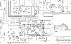
I am referring to a group of four transistors TR304 through TR307, marked in red in the schematics below. I had to split this into two pics to show the entire circuit. The first pic shows that a lead straight off the secondary of the transformer which (I believe) is half-wave rectified and run through a couple resistors, feeds the base of TR304.
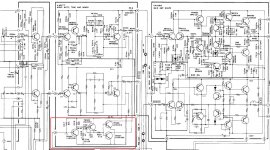
Please correct me if any of my assumptions are incorrect. The second pic shows that the outputs of TR306 and TR307 connect to the outputs of the Tone Amp.
What is the purpose of this circuit? Thanks in advance...")
I am referring to a group of four transistors TR304 through TR307, marked in red in the schematics below. I had to split this into two pics to show the entire circuit. The first pic shows that a lead straight off the secondary of the transformer which (I believe) is half-wave rectified and run through a couple resistors, feeds the base of TR304.
Please correct me if any of my assumptions are incorrect. The second pic shows that the outputs of TR306 and TR307 connect to the outputs of the Tone Amp.
What is the purpose of this circuit? Thanks in advance...
Attachments
Last edited:
It would work with 47uf. It would just have a bit longer delay. It’s places like that that I don’t like using electrolytic caps. They get a little leaky and the circuit can get flaky or refuse to turn on at all. I prefer X7R ceramics, and never have to change/question them again. Why doesn’t the manufacturer use then? In that size they are about $2 as opposed to 2 cents.
Most amps have relays because they can also be used to protect speakers in the case of a shorted output transistor.
Most amps have relays because they can also be used to protect speakers in the case of a shorted output transistor.
It would, but would stay muted for longer.The value of C312 is 22uF. Is this value critical? Would the circuit function correctly with a 47uF cap instead of 22uF?
wg_ski has a point, though I imagine that using a low leakage series electrolytic would be just fine as well... in fact I'd envision few problems even with some ordinary Panasonic FCs.
OK, thanks again adason, rayma, and wg-ski 
one last question about this circuit if I may...
Are any of these transistors in full saturation the whole time the amp is on? Or do they operate only at power on/off?
I ask this because I know that in relay circuits, one of the transistors that operates the relay is in full saturation continuously while the amp is on. And over a long period of time, this transistor's hFe becomes lower, and at some point will need to be replaced for the circuit to function.
Is something similar happening with any (or all) of the transistors in this muting circuit?
EDIT: thanks to sgrossklass also, who posted while I was typing
Last edited:
Those transistors function as switches. For example, the two final transistors saturate,
and short the audio lines to ground, when muting. During normal operation all of the
transistors in that muting circuit are off (open). The timing capacitor is the weak point.
When it gets leaky, the muting time may become very long, or even eternal.
and short the audio lines to ground, when muting. During normal operation all of the
transistors in that muting circuit are off (open). The timing capacitor is the weak point.
When it gets leaky, the muting time may become very long, or even eternal.
Last edited:
Saturation doesn’t do anything bad to a transistor. Reverse biasing the base-emitter into breakdown does degrade the Hfe (and make it noisy). The muting transistors usually have a high vebo spec for that reason - so that reverse breakdown doesn’t happen with large audio signals. The transistors won’t usually go bad, especially if not exposed to the outside world such as on an input jack.
It would, but would stay muted for longer.
wg_ski has a point, though I imagine that using a low leakage series electrolytic would be just fine as well... in fact I'd envision few problems even with some ordinary Panasonic FCs.
FC is what I will put in my next Mouser order. Likely better than that original cap that has worked fine for forty years.
Saturation doesn’t do anything bad to a transistor. Reverse biasing the base-emitter into breakdown does degrade the Hfe (and make it noisy). The muting transistors usually have a high vebo spec for that reason - so that reverse breakdown doesn’t happen with large audio signals. The transistors won’t usually go bad, especially if not exposed to the outside world such as on an input jack.
More good info. Thanks
Not sure if this is relevant, but I always turn down any amp before powering down, and stop the source signal as well. No music signal to make/break anywhere in the amp. I was thinking about power switches, but it seems that this would apply to the muting circuit as well.
- Status
- This old topic is closed. If you want to reopen this topic, contact a moderator using the "Report Post" button.
- Home
- Amplifiers
- Solid State
- Can someone help me understand what this circuit does?