Sometimes ,you need to circum navigate the planet to find out, it was just behind your shoes.
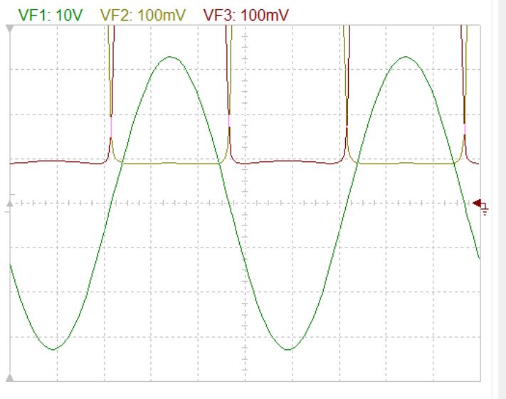
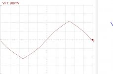
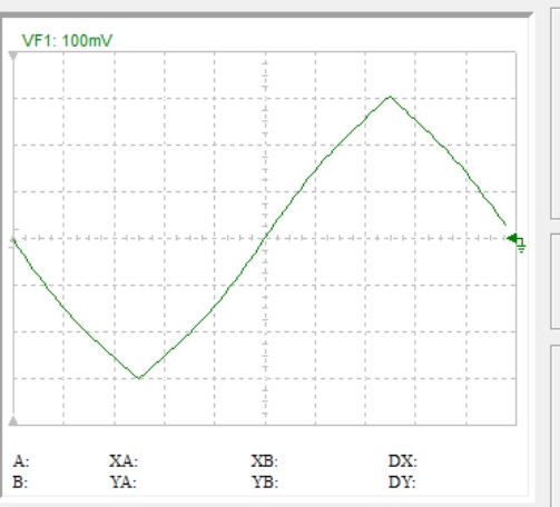
The quiescent bias current is 145ma . As you can observe on scope , the minimum current falls to 90ma at 32.8 vp on 8 ohms with 33vp input 1khz, with Dtot of 0.04% .
The quiescent bias current is 145ma . As you can observe on scope , the minimum current falls to 90ma at 32.8 vp on 8 ohms with 33vp input 1khz, with Dtot of 0.04% .
Attachments
Last edited:
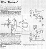
I don't see any resemblance to Bloomley.
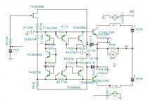
If you replace the floating bootstrapped supplies with the rails , you get a standard compound darlington driver. It works the same, on condition you have very very high early transistors. The compound can be replaced by simple darlington.
In this circuit , not only there is no cut-off , but also the voltage drop output/input is decreased . Note, 32.8v output/33v input, hence decrease in distortion. If I can get the currents in R1,R2 constant than the output follows exactly the input, the distortion goes to zero, the output impedance also.
Attachments
Last edited:
Hi kokoriantz,
That is very interesting!
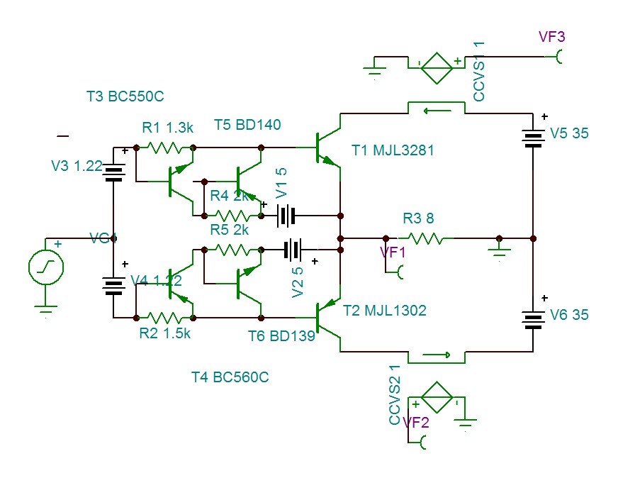
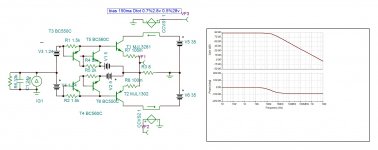
Attached is an LTspice version.
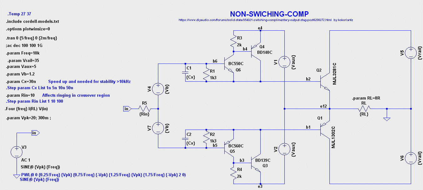
It uses a CFP driver with +/-5V auxiliary sources.
R1 and R2 provide the current to the bases of the power transistors, so when one CFP side turns off there is always some base current and therefore some collector current in the power transistors.
C1 and C2 have been added because oscillation occurs when driven by 10kHz and 20nF seems to stop oscillation (at least in the simulation). Oscillations comes from using the CFP arrangement. I hope you can see the oscillation in your Tina circuit also.
The idle current is also very sensitive to the power transistors junction temperature. Some emitter resistance may be needed to stop thermal runaway even with a pair of thermaltraks and of course if paralleled.
These capacitors provide some charge pull-out for the power transistors. Also R5 is added to see how much source resistance affects stability and ringing. R5 in the 1-10 ohm range seems to make stability worse; above that there's not much effect on stability - a bit like a base stopper.
As shown it appears to work OK up to about 50kHz with 30nF caps. Above that cross conduction increases and THD increases.
That is very interesting!
Attached is an LTspice version.
It uses a CFP driver with +/-5V auxiliary sources.
R1 and R2 provide the current to the bases of the power transistors, so when one CFP side turns off there is always some base current and therefore some collector current in the power transistors.
C1 and C2 have been added because oscillation occurs when driven by 10kHz and 20nF seems to stop oscillation (at least in the simulation). Oscillations comes from using the CFP arrangement. I hope you can see the oscillation in your Tina circuit also.
The idle current is also very sensitive to the power transistors junction temperature. Some emitter resistance may be needed to stop thermal runaway even with a pair of thermaltraks and of course if paralleled.
These capacitors provide some charge pull-out for the power transistors. Also R5 is added to see how much source resistance affects stability and ringing. R5 in the 1-10 ohm range seems to make stability worse; above that there's not much effect on stability - a bit like a base stopper.
As shown it appears to work OK up to about 50kHz with 30nF caps. Above that cross conduction increases and THD increases.
Attachments
Some mods
Hi kokoriantz,
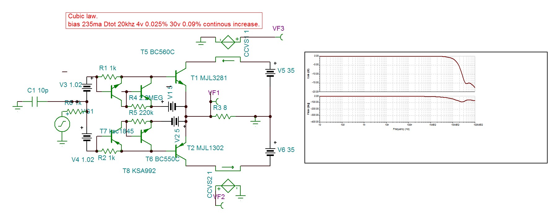
A simple mod to your circuit gives Cube-law Class-AB. Removing the CFP driver base-emitter resistors R3 and R4.
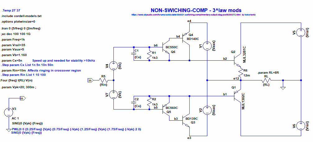
Removing these resistors spreads the CFP turn on over a wider voltage range which also improves the HF stability. The bias voltage was reduced slightly to get 250mA at idle. The non-switching current is the same as before.
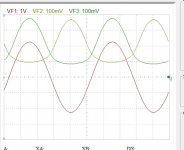
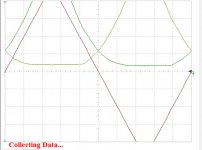
The plot below shows the cube-law region with a triangle input and using common emitter (as suggested by Pawel in the post above). With cube-laws the collector currents increase to about 8 times the idle current (2^3=8) before the other side Gm goes to zero (still with some collector current though).
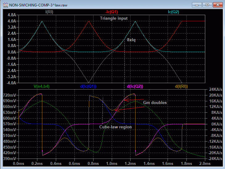
When biased for Cube-laws the distortion does not contain much high order harmonics in the crossover region and the crossover region extends to a much higher power level than standard biasing making it a good choice for audio sq. and close to Class-A but with a lot less idle current - around 8 times less heat than pure Class-A!
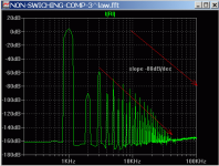
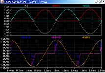
The FFT below shows the harmonics are dominated by the 3rd harmonic (being cubelaw-ish) and the higher harmonics fall away very fast, in this case around -80dB/decade as frequency increases which is much faster than for a standard output stage (typically around -40dB/decade) and therefore sounding more like pure Class-A amps.

I think this idea could be used in a practical amp if all temperature effects are well controlled. All the best with it.
Hi kokoriantz,
A simple mod to your circuit gives Cube-law Class-AB. Removing the CFP driver base-emitter resistors R3 and R4.
Removing these resistors spreads the CFP turn on over a wider voltage range which also improves the HF stability. The bias voltage was reduced slightly to get 250mA at idle. The non-switching current is the same as before.
The plot below shows the cube-law region with a triangle input and using common emitter (as suggested by Pawel in the post above). With cube-laws the collector currents increase to about 8 times the idle current (2^3=8) before the other side Gm goes to zero (still with some collector current though).
When biased for Cube-laws the distortion does not contain much high order harmonics in the crossover region and the crossover region extends to a much higher power level than standard biasing making it a good choice for audio sq. and close to Class-A but with a lot less idle current
- around 8 times less heat than pure Class-A!The FFT below shows the harmonics are dominated by the 3rd harmonic (being cubelaw-ish) and the higher harmonics fall away very fast, in this case around -80dB/decade as frequency increases which is much faster than for a standard output stage (typically around -40dB/decade) and therefore sounding more like pure Class-A amps.
I think this idea could be used in a practical amp if all temperature effects are well controlled. All the best with it.
Attachments

Hi!
If you connect T1,2 emiters to the ground and take Vout from between the power supply, you will get the gain and beautifull current out nsw amp,
congrats!
PS is it some kind of Bloomley topology?
Hi Kokoriantz,
I tried this using Ian's circuit, it needs more linearity...
Attachments
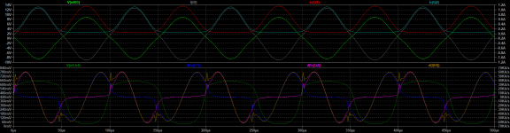
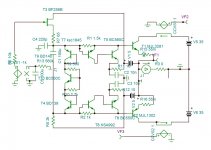
hello Jan . I feel "heel blij "that you find this circuit interesting . I am trying out to be used conventional output stage with high impedance VAS . With modest 33k to start with. Look what miracles can happen , it has no pole !! . I degenerated for paralleling ,still good results. I will try in cube form. To remind the purpose of non-switching , that at high slew rates the transistors switch much faster , hence no gliches. See the 100khz .
https://www.diyaudio.com/forums/attachment.php?attachmentid=843312&stc=1&d=1589274637

https://www.diyaudio.com/forums/attachment.php?attachmentid=843312&stc=1&d=1589274637
Attachments
Last edited:
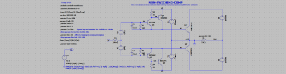
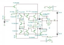
This is low impedance version 1k with cubic rule as suggested by Ian. It needed 220k to get the minimum distortion . Once the bias is adjusted at half slope , the bias voltage 2×1.02v remains constant while the R4,R5 can be adjusted.
I never got problems with stability . The KSA992/C1845 are very low current transistors better suited here.
I never got problems with stability . The KSA992/C1845 are very low current transistors better suited here.
Attachments
Instability
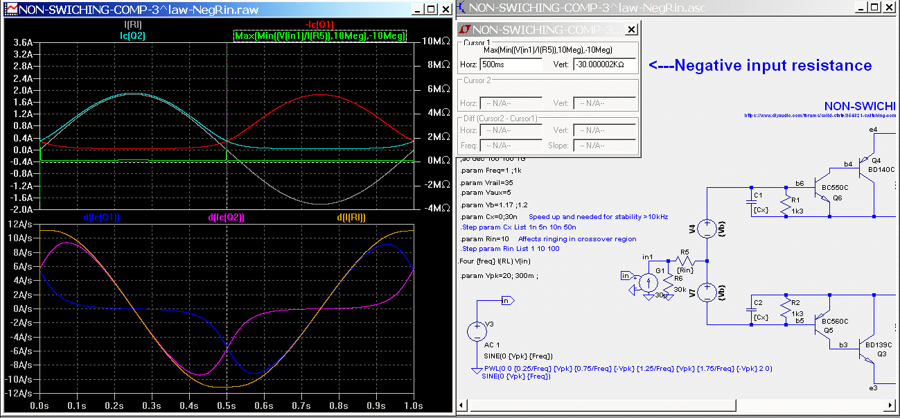
Hi kokoriantz,
SPICE does not always show oscillations. The timestep is done automatically if you don't specify it and the value it uses can be longer than the oscillation period so it looks stable, but if you up the input frequency or set the Maximum timestep small enough then the oscillation can be seen.
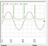
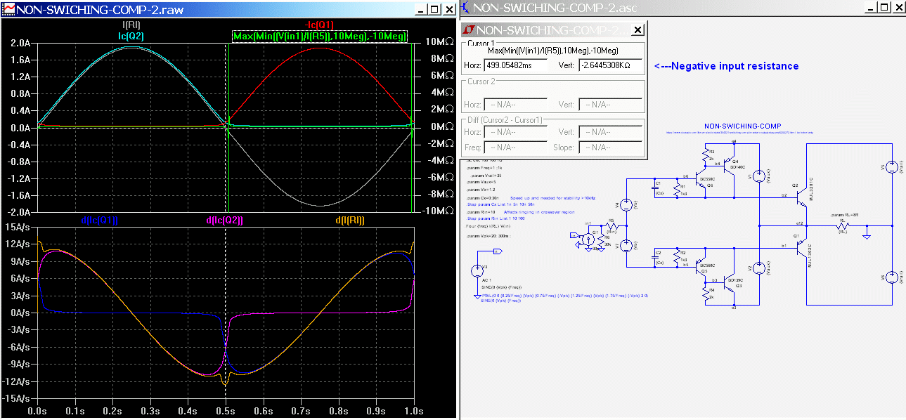
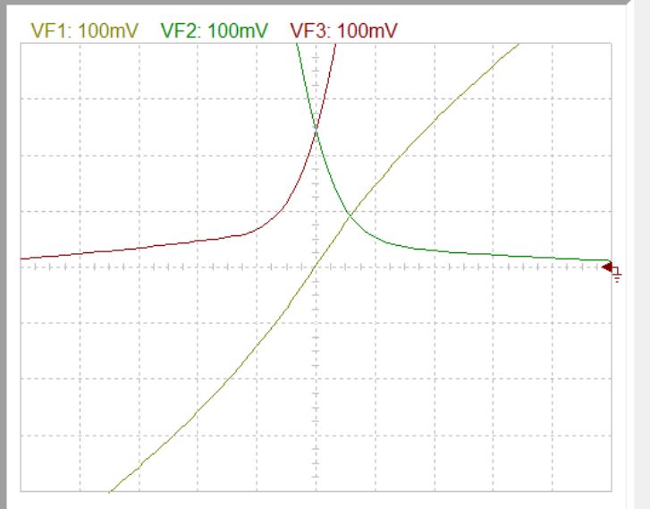
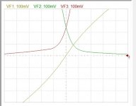
Attached files shows negative resistance is generated by the circuit near the zero cross. I've no idea why. But this could be a cause for oscillation with some loads. The negative input resistance appears just after the zero cross. Normally it around 130k positive ohms.
.
The plot below shows negative resistance in the Cube-law version. Notice the Cube version does not have the gain blip near the zero cross. This means the high order harmonics have been suppressed and the sound quality is much improved using the alternative, requiring less overall feedback to remove this distortion.
With a Cube-law output stage the higher harmonics fall off so quickly with frequency that you only need to use a small amount of negative feedback to remove the output stage distortion from being heard. With the fast roll-off in higher harmonics only 30dB of negative feedback is needed to make all harmonics inaudible. This amount of feedback can be had from the follower itself, which gives around 0.05% THD, and I have found that that is low enough with a Cube-law output stage.
But if you have a gain blip in there (like above) then you will need the usual extra 30dB of global feedback (in the 1-10kHz region) on top of the output stage 30dB to suppress the higher harmonics.
...I never got problems with stability[/IMG]
Hi kokoriantz,
SPICE does not always show oscillations. The timestep is done automatically if you don't specify it and the value it uses can be longer than the oscillation period so it looks stable, but if you up the input frequency or set the Maximum timestep small enough then the oscillation can be seen.
Attached files shows negative resistance is generated by the circuit near the zero cross. I've no idea why. But this could be a cause for oscillation with some loads. The negative input resistance appears just after the zero cross. Normally it around 130k positive ohms.
.
The plot below shows negative resistance in the Cube-law version. Notice the Cube version does not have the gain blip near the zero cross. This means the high order harmonics have been suppressed and the sound quality is much improved using the alternative, requiring less overall feedback to remove this distortion.
With a Cube-law output stage the higher harmonics fall off so quickly with frequency that you only need to use a small amount of negative feedback to remove the output stage distortion from being heard. With the fast roll-off in higher harmonics only 30dB of negative feedback is needed to make all harmonics inaudible. This amount of feedback can be had from the follower itself, which gives around 0.05% THD, and I have found that that is low enough with a Cube-law output stage.
But if you have a gain blip in there (like above) then you will need the usual extra 30dB of global feedback (in the 1-10kHz region) on top of the output stage 30dB to suppress the higher harmonics.
Attachments
Last edited:
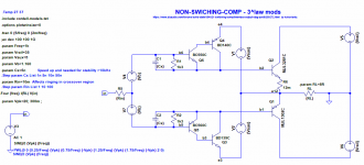
R6 adjusts the offset, R10 the bias. The bd transistors are screwed upon the outputs to capture the junction temperature . I have 50w square law biased c5200/a1943 at 0.9A since over ten years , but of course it needs to see if R8 needs to be replaced by CC , as CLD 2ma. The performance is identical as precedent but with higher input impedance. The time response got a hit due to output to input feedback by supplies . Temporarily I stabilized by caps , but I have precedent experience from Simple high power BJT/MOSFET G=0.6db output with Hawksford error corrector . where I resolved with 20 ohms and a capacitor on the driver.
I tried the negative impedance on the same version but with cube law.
With my modest Tina I injected 10hz 4v triangular plus 100khz 30mv signals and observed the 100khz several cycles , I saw nothing wrong.
Attachments
Hi!
If you connect T1,2 emiters to the ground and take Vout from between the power supply, you will get the gain and beautifull current out nsw amp,
congrats!
PS is it some kind of Bloomley topology?
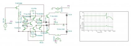
I tried for you in transnova. To have a DF of 16 the gain is only 3.5, the distortion at 17w is 0.35% mainy odd harmonics. But wait a minute , odd harmonics yes,but of opposite phase if you please. These harmonics will decrease the distortion of you speaker and enhance the dynamic , but who on earth would believe me ?
Attachments
Sorry for the error.
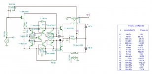
As it has high DF of 68 up to 200khz , 3Mhz response with 10k source, 0.025%Dtot at 20khz , what ask better ? It only needs a voltage gain . A triode can be sufficient . I clarify that I am dealing with two versions , An alone standing output stage, and one ,making part of standard 3 stage amp output stage that I will deal next.
As it has high DF of 68 up to 200khz , 3Mhz response with 10k source, 0.025%Dtot at 20khz , what ask better ? It only needs a voltage gain . A triode can be sufficient . I clarify that I am dealing with two versions , An alone standing output stage, and one ,making part of standard 3 stage amp output stage that I will deal next.
Attachments
Now that I have a working circuit , I wanted to give more approached detailed view. First the MJL models do not include the internal emitter resistors, about 0.045 ohms. If I add 0.01 extra for linking , 0.055 ohm degenerate each emitter. The IC/Vbe of the P type is lower than the N, to balance the mismatch The sense resistor needs to be higher . A quick readjustment gives bias at 200ma . In cubic law the output impedance should give an clean S , Ihave some work need on it ,see below .
Attachments
Hi kokoriantz,
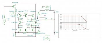
I tried to repeat your circuit (post 16) in LTspice. Files attached.
I get a glitch in the gain giving only 0.1 THD at 1kHz (plots below): Set for same 200mA at idle.

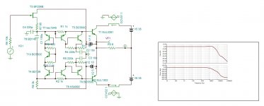
Changing capacitors did not help. Removing the base-emitter resistors on T5 and T6 removed most of the gain glitch (below):
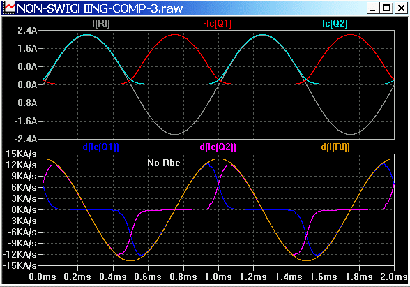
If you monitor the derivative of currents you will see these irregularities better. I think in Tina you use a CCVS (the ones already present) driving a capacitor (1uF maybe) and plot I(C). You may need to add a 1u ohm series resistance to the capacitor.
BTW if you use this as a follower (tube driver gain stage) with no global feedback then would you need the jFET? Wouldn't a tube driver be able to drive it without it?
I tried to repeat your circuit (post 16) in LTspice. Files attached.
I get a glitch in the gain giving only 0.1 THD at 1kHz (plots below): Set for same 200mA at idle.
Changing capacitors did not help. Removing the base-emitter resistors on T5 and T6 removed most of the gain glitch (below):
If you monitor the derivative of currents you will see these irregularities better. I think in Tina you use a CCVS (the ones already present) driving a capacitor (1uF maybe) and plot I(C). You may need to add a 1u ohm series resistance to the capacitor.
BTW if you use this as a follower (tube driver gain stage) with no global feedback then would you need the jFET? Wouldn't a tube driver be able to drive it without it?
Attachments

Any conception follows spiral pattern and not a linear start-finish way. Now,that the circuit has realistic function , I am looking for it's cubic character, the main reason of its existence . To say that , I abandoned the class A world , to harvest from class B amplifiers odd order harmonics of opposite phase . My first trial was ClassB+a mosfet amplifier . It is good ,but even low biased , the square law function clears the needed harmonics at low level . To get a cubic function, the second derivative of output V/I , that is the output impedance, should be a constant . The circuit has the possibility by 3 adjust , the bias R10, the gains R1,R2 , and the asymmetries R4,R5 , to create the cubic function . The last adjustment shows this
Tomorrow , I will work with output impedance rather with numbers than graph to bring fine adjustments, than I must find a method , how a diy can adjust these five resistors.
I greatly appreciate your team work looking of other aspects of the project . For now it is in gestation , once the amp is born , the fin details can be dealt with all together.
The jfet. The amp without it needs 1k impedance source for low distortion.
Attachments
Last edited:
Hi kokoriantz,...The jfet. The amp without it needs 1k impedance source for low distortion.
I'm pleased to help. I'd been looking at another way to keep the power transistors on a small amount (aka non-switching) with a follower type output stage. Your way seems relatively easy; and the surprise for me is that it can give cube-laws in open loop (common emitter) when biased just right.
I checked the circuit without the jFET and the distortion is about 2% with 20Vpk output -- then with the jFET it is 0.1%. So the jFET does some magic
 - I haven't figured out how just yet.
BTW in my last post the gain glitch from the base-emitter resistors on T5 and T6 can be removed by adding about 2uA from base T5 to base T6. That's with the resistors present. The current source keeps T5 and T6 on (aka non-switching). It also increases the non-switching current in the power transistors from 15mA to 30mA but 'tis is well worth it. LTspice file attached.
Attachments
Good morning Ian.
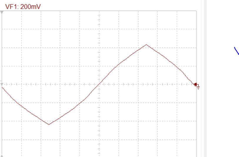
I realized That my measuring method was wrong , I was neglecting to readjust the offset at every modification . Once a servo is added , I re started from your suggestion 1k sense and no degenerating resistors . The upper pole adjusted higher gain and it gave perfectly symmetrical ,looks cubic function ,with about 240ma.
This is transfer function of the amp with 4A p, but the with Vce constant. Today I will see will 8 ohm load .
Attachments
- Status
- This old topic is closed. If you want to reopen this topic, contact a moderator using the "Report Post" button.
- Home
- Amplifiers
- Solid State
- Non-switching complimentary output stage