I'm very sorry, I make the mistake for the above connection. I take the AC input is not correct, the Fuse side should be the AC output and control by the power relay, so that in this case there is no AC output form the Fuse.
I make the correct connection diagram again.
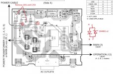
Please also remove C254 for safe and connect the diodes like the diagram.
Very sorry for this.
I make the correct connection diagram again.
Please also remove C254 for safe and connect the diodes like the diagram.
Very sorry for this.
Attachments
Last edited:
Aha! I just found Q251 was what blew lucky I have a few of those.
My fault, cause Q251 burn, C254 charge it to burn.
I'm sorry for my careless!
The diagram updated again.
Last edited:
I'm very sorry, I make the mistake for the above connection. I take the AC input is not correct, the Fuse side should be the AC output and control by the power relay, so that in this case there is AC output form the Fuse.
I make the correct connection diagram again.
Please also remove C254 for safe and connect the diodes like the diagram.
Very sorry for this.
Oh, now I see, its viewed from the solder side so I have the jumper backwards?
Oh, now I see, its viewed from the solder side so I have the jumper backwards?
It should remove C254 and jumper J261, and connect the diodes to point A and B(diodes does not connected between J261)
Attachments

Last edited:
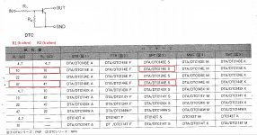
I first check DTC114ES are also NPN and don't know the resistors network value inside the transistor is compatible to DTC144ES or not.
This transistor is a reset control function(drive signal to ground), I think it will not cause any problem for our test if it is left in the PCB.
This transistor is a reset control function(drive signal to ground), I think it will not cause any problem for our test if it is left in the PCB.
Last edited:
I got 17Vac on the transformer output and no S10 of course. Oh well, you cant say we didn't try? I will order all the parts it needs and get it going. Thanks for helping me understand this part of the startup Patrick. It's appreciated.
Ok, it is so right to repair the amp in this way. I hope you get all the new parts and fixed the amp.
Ok, it is so right to repair the amp in this way. I hope you get all the new parts and fixed the amp.
I thought it was great testing it to see what would happen? I had fun doing it too. You are a good bloke Patrick, thanks mate.
I just got the last part I needed to get this amplifier going in the post. I ended up replacing just about every component on the board except for the small transformer? The little 2K3850 FET cost me $26.50 including postage. I could have bought 5 x 2K3850 FETs from China for $3.29 but as they say ''once bitten twice shy''. I replaced the 4013 flip flop IC as well. All this looks to me like it was caused by a shorted mylar capacitor? Anyway, I have a much better understanding of how these switches work now so it was all worth it and thanks again for your help, Patrick.

- Status
- This old topic is closed. If you want to reopen this topic, contact a moderator using the "Report Post" button.
- Home
- Amplifiers
- Solid State
- Yamaha RX-497 No main power?