Hello friends.
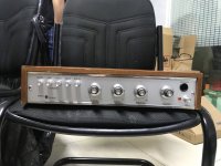
I have a MetroSound ST20 amplifier that has a "pop" sound when the power button is turned on, when the volume is turned down, the left speaker is still very low.
In your opinion, how to solve this problem.
I have a MetroSound ST20 amplifier that has a "pop" sound when the power button is turned on, when the volume is turned down, the left speaker is still very low.
In your opinion, how to solve this problem.
Attachments
This looks to be an old AC or capacitor coupled amplifier. Assuming that is so...
then I suspect the problem may be a failed output stage and you are simply hearing the speaker pop as it draws a high current momentarily through the speaker coupling cap.
First check would be to see if the 'midrail' voltage is correct. Look for the speaker coupling caps and measure the DC voltage (compare channels) on the input side of the cap (usually the PLUS side).
This voltage should be approx one half the total supply voltage (the voltage you see across the big cap in the power supply). Look for one channels midpoint being either very high or very low.
This looks to be an old AC or capacitor coupled amplifier. Assuming that is so...
then I suspect the problem may be a failed output stage and you are simply hearing the speaker pop as it draws a high current momentarily through the speaker coupling cap.
First check would be to see if the 'midrail' voltage is correct. Look for the speaker coupling caps and measure the DC voltage (compare channels) on the input side of the cap (usually the PLUS side).
This voltage should be approx one half the total supply voltage (the voltage you see across the big cap in the power supply). Look for one channels midpoint being either very high or very low.
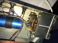
I tested the voltage on the left channel is 10v, I am also conducting the replacement of the capacitors including 1 power capacitor and 47uf capacitor
You need to first see what the total supply voltage is as I mentioned earlier. It might be around 30 to 40 volts DC (that would be a typical value for a modest amp).
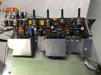
Do you see the four output transistors bolted to the heatsink. It looks like all four are of the same type which means the design is a 'quasi complementary' using NPN output devices.
The middle leg of one of a pair should have the supply voltage present.
The middle leg of the other in the pair should have half that voltage present.
Be EXTREMELY careful not to short the pins if you attempt to measure here. One slip and it will all go bang and cause damage.
You need to determine the fault before randomly swapping caps.
You need to either insert an ammeter into the output transistor circuit which can be done on either transistor of the pair and can be either collector or emitter of either. That should work but extreme care is needed. Unless you are totally comfortable doing that I would not recommend that method.
Much easier is to see if it has any low value 'emitter resistors' and to calculate the current from the voltage across the resistor. Without a circuit diagram only you can do that by visually looking.
Much easier is to see if it has any low value 'emitter resistors' and to calculate the current from the voltage across the resistor. Without a circuit diagram only you can do that by visually looking.
hi mooly ,I have a circuit diagram, but I'm a beginner and don't understand it very well. I can send the circuit diagram and the pictures of the amplifier, and then let you point out the steps. Thank you,You need to either insert an ammeter into the output transistor circuit which can be done on either transistor of the pair and can be either collector or emitter of either. That should work but extreme care is needed. Unless you are totally comfortable doing that I would not recommend that method.
Much easier is to see if it has any low value 'emitter resistors' and to calculate the current from the voltage across the resistor. Without a circuit diagram only you can do that by visually looking.
Attachments
That's an easy one. Connect your meter across either one of these 0.5 ohm resistors. It doesn't matter which.
30 milliamps current will give 15 millivolts DC across the resistor. Its a very small voltage so make sure your meter is set correctly on DC volts. Adjust the preset to give that value.
No signal present when adjusting and be sure to get a good connection of the probes to the resistor.
30 milliamps current will give 15 millivolts DC across the resistor. Its a very small voltage so make sure your meter is set correctly on DC volts. Adjust the preset to give that value.
No signal present when adjusting and be sure to get a good connection of the probes to the resistor.
Attachments
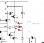
你好,直接电流表的红笔要接触正负端。我的万用表已调整为测试 50mA 档位。仔细画。谢谢,这很容易。将您的仪表连接到这些 0.5 欧姆电阻器之一。哪个没关系。
30 毫安电流将在电阻器上产生 15 毫伏直流电。它的电压非常小,因此请确保您的仪表正确设置为直流电压。调整预设以给出该值。
调整时没有信号存在,并确保探头与电阻器的连接良好。
English please ")
Your meter MUST be on DC voltage, not current. You are measuring the voltage ACROSS the 0.5 ohm.
Ohms law tells us that 30ma current will produce 15 millivolts across 0.5 ohm.
V=I*R which is 0.03*0.5 = 0.015 volts (15 millivolts)
Hello, the red pen of the direct ammeter is going to touch the positive and negative ends. My multimeter has been adjusted to test 50mA gears. Draw carefully. Thank you
Your meter MUST be on DC voltage, not current. You are measuring the voltage ACROSS the 0.5 ohm.
Ohms law tells us that 30ma current will produce 15 millivolts across 0.5 ohm.
V=I*R which is 0.03*0.5 = 0.015 volts (15 millivolts)
English Please jacky.Yes, the circuit diagram is labeled 30mA current and should be DC current. Is the two red arrows you mark refer to positive negative? thanks,
dave

diyAudio moderation team
Yes, the circuit diagram is marked with a 30mA current, which should be DC current. Do the two red arrows you mark point to the positive and negative poles? Thank you
Polarity of the probes does not matter for this. One way round will show +15mv and the other way around will show -15mv. Just ignore the - and +.
Polarity of the probes does not matter for this. One way round will show +15mv and the other way around will show -15mv. Just ignore the - and +.
Thank you for your help. I measured that the AC voltage of R10 and R19 is 2.1mv, and the two channels are the same. But I want to know whether the static DC current is adjusted for the test of points a, B, C and D mentioned in the drawing?
I'm busy ahead. They all speak Chinese. I'm sorry, Mr. policeman,English Please jacky.
dave
diyAudio moderation team
I measured that the AC voltage of R10 and R19 is 2.1mv, and the two channels are the same.
It is DC voltage you are measuring, NOT AC volts. You are going to end up damaging this if you do it incorrectly.
Measure the DC voltage across either 0.5 ohm resistor and adjust for 15 millivolts DC across the resistor.
I measured that the millivolt voltage of this resistance is 1.9mv, which should be normal. There are no other problems. Thank you for your help. It's great,It is DC voltage you are measuring, NOT AC volts. You are going to end up damaging this if you do it incorrectly.
Measure the DC voltage across either 0.5 ohm resistor and adjust for 15 millivolts DC across the resistor.
thank of your helpI don't think you are understanding the process tbh
- Home
- Amplifiers
- Solid State
- MetroSound ST20 amplifier hears the sound when the power button "pops"