The Cambridge Audio P500 and A500 (and others?) have an LED in the power amp - one for each channel.
I'm not sure of the function of those; I think they are used as a voltage reference?
Please see attached schematic.
How much current should be flowing through that LED? Should it be fully bright?
I'm a beginner with solid state circuits. Can anybody explain to me what that LED is doing? Thanks!
In the P500 I'm working on, the LEDs are barely glowing. Is this normal or should they be replaced?
Attachments
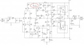
The LED was used as voltage reference for constant current sources Q213 / Q214. It is recommended to run through the same min. 5mA (for minimum noise) and slightly more (for as little dynamic impedance). Through the D211 with a + 45VDC supply voltage across the green LED it will be about 2VDC, so the current through it will be just over 9mA. It should be completely bright at that current ... check voltage across D211 (~ 2VDC) as well as voltage across resistor R245 (~43VDC).
Can anybody explain to me what that LED is doing?
If we neglect the small base currents of Q213 and Q214, then we can just look at D211 and R245.
Since the LED drop is about 2V, this makes the drop across R245 to be 45V - 2V = 43V.
Then the current through R245 (and the LED) is 43V / 4.7k = 9.15mA, a typical current for an LED.
This LED string is used to bias Q213 and Q214, which are each used as (separate) current sources.
Since the 2V LED is in parallel with the series string of R243 and the BE junction of Q213
(which always drops approx. 0.6V), the voltage across R243 is 2V - 0.6V = 1.4V. Then the current
through R243 is 1.4V / 820 = 1.7mA. This is the tail current for the diff amp (Q212 and Q222),
since the emitter current is close to the collector current in a transistor.
This tail current is equally split between Q212 and Q222, since they use a current mirror (Q220, Q221).
Last edited:
Thanks, folks- much appreciated.
Those red LEDs look quite dim, so I will replace with similar size red LEDs....after checking the voltages as per the suggestions.
I'll update the thread as the job proceeds.
I'll get back to the amp project tomorrow.
On today's ToDo list is : Reinstall kitchen sink!
")
Those red LEDs look quite dim, so I will replace with similar size red LEDs....after checking the voltages as per the suggestions.
I'll update the thread as the job proceeds.
I'll get back to the amp project tomorrow.
On today's ToDo list is : Reinstall kitchen sink!
Those red LEDs look quite dim, so I will replace with similar size red LEDs....
after checking the voltages as per the suggestions.
I would not change the LEDs, they are (very) likely working exactly like the mfr wants them to work.
You might change the bias current from what they intend.
Last edited:
NO PLEASE.Thanks, folks- much appreciated.
Those red LEDs look quite dim, so I will replace with similar size red LEDs....after checking the voltages as per the suggestions.
I'll update the thread as the job proceeds.
They are working as intended: voltage references.
Light emission is IRRELEVANT, why do you worry or care about that?
They illuminate nothing, they are not even pilot indicator lights.
In fact I guess they are not even seen from outside.
Many PCBs carry extra "Easter Egg" text etched and printed on them, a popular one is: "What are you doing here? You have just voided your warranty"
Your amp should have included a similar warning.
Last edited:
NO PLEASE.
They are working as intended: voltage references.
Light emission is IRRELEVANT, why do you worry or care about that?
They illuminate nothing, they are not even pilot indicator lights.
In fact I guess they are not even seen from outside.
Many PCBs carry extra "Easter Egg" text etched and printed on them, a popular one is: "What are you doing here? You have just voided your warranty"
Your amp should have included a similar warning.
Exciting discussion!!
Thanks for all the comments.
In another thread, about a different Cambridge Audio amplifier which also uses LEDs as voltage references (I think..):
Cambridge Audio A3i repairs and mods
The designer of the amplifier, x-Pro said:
I will use this opportunity to make a full list of modifications for the A3i.
For both performance and reliability:
1) All 4 LEDs replaced with a high temperature type green or yellow colour, lifted at least 15 mm from the PCB.
He also advised a person trying to repair his amplifier to replace an LED even though it was still glowing dimly.
I think the idea was that the hot environment near the LED would cause it to fail eventually, and that the dimming was a warning sign.
That was the reason I asked the question about the P500 and A500.
BTW, those units are well past any idea of warranty, I think. They are 'budget' 80s components which were probably headed for 'the dump' when I bought them.
I fixed the P500 (rewound the power transformer) and it's working now. I posted a thread about that. I was thinking about other 'maintenance and upgrade' items before I put the cover back on it.
I don't think an amp using a LED with 9~10ma for a voltage reference is a good idea, LED more easy fail in this usage and replacement LED voltage may be different and it will change the original circuit's current values.
Using diodes, zener diodes or transistors as diodes are better for this kind of application.
Using diodes, zener diodes or transistors as diodes are better for this kind of application.
Last edited:
How much current should be flowing through that LED? Should it be fully bright?
In this circuit, you need to confirm the LED voltage drop, it is around 2v at the base of Q213 and Q214 from +v supply rail, with this correct base voltage, the current supply form Q213 and Q214 will be correct for the amp circuit.
Last edited:
Thanks, folks- much appreciated.
Those red LEDs look quite dim, so I will replace with similar size red LEDs....after checking the voltages as per the suggestions.
I'll update the thread as the job proceeds.
I'll get back to the amp project tomorrow.
On today's ToDo list is : Reinstall kitchen sink!
Outside of the LEDs are dim, is the amp doing anything wrong? Did you measure the value of R245 which sets the LED current ? If it ain't broke...
G²
Talking about the A3i which uses green LEDs, X-Pro (the designer) suggested using a string of 3 diodes to replace the LED, as an alternative.Using diodes, zener diodes or transistors as diodes are better for this kind of application.
I'd think that diodes would be 'tougher' in a warm area of the amp?
I'm busy with a kitchen project right now; I'll get back to the amp and make some measurements in a day or two.
- Status
- This old topic is closed. If you want to reopen this topic, contact a moderator using the "Report Post" button.
- Home
- Amplifiers
- Solid State
- Cambridge Audio P500 A500 power amp LED brightness?