Hi
Because of the world situation (like a fiction catastrophic movie but ...it is real now ) I need to change my mind focus so why not develop a new class A power amp based on parts I already have.
I have selected USSA-3 amp because I had already developed 3 variants of the USSA-5 amp base on different transistors choices.
USSA-5 PCB GB
So this time is also a variant but from the original USSA-3 amp which by the way uses the same pcb as the USSA-5.
The difference between version 3 and 3B (B stands for bjt):
USSA-3: jfet input, mosfet drivers and lateral mosfet output
USSA-3B: jfet input, bjt driver, bjt output
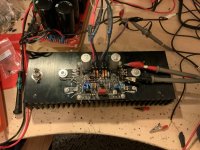
I must advise that it has not been heard yet but only one prototype and still in tweaking mode on my bench. However, after some tweakings I got very satisfying performance results based on my expectations.
I wanted to get a higher damping factor than the original vetsion 3 and I got similar damping factor as the USSA-5.
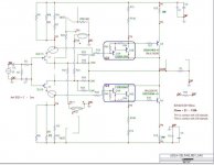
The main advantage is to not have to use the matched obsolete mosfet drivers. I have not finished the adjustments and still some errors on the schematics but it shows the idea. PSU is +/-24vdc for about 25Wrms in class A.
Both USSA-3 and -3B have H2 level adjustment using P3 pot.
Jfet IDss tolerance matching requirements between N and P channel is <10% so not very tight. However, they need to have similar IDSS between left and right pcb.
Warning: the bjt output version has no over current protection as opposed to the version with lateral mosfet output.
See some snapshots:
IQ5/Q6 should read IQ3/4.
Fab
Because of the world situation (like a fiction catastrophic movie but ...it is real now
) I need to change my mind focus so why not develop a new class A power amp based on parts I already have. I have selected USSA-3 amp because I had already developed 3 variants of the USSA-5 amp base on different transistors choices.
USSA-5 PCB GB
So this time is also a variant but from the original USSA-3 amp which by the way uses the same pcb as the USSA-5
.The difference between version 3 and 3B (B stands for bjt):
USSA-3: jfet input, mosfet drivers and lateral mosfet output
USSA-3B: jfet input, bjt driver, bjt output
I must advise that it has not been heard yet but only one prototype and still in tweaking mode on my bench. However, after some tweakings I got very satisfying performance results based on my expectations.
I wanted to get a higher damping factor than the original vetsion 3 and I got similar damping factor as the USSA-5.
The main advantage is to not have to use the matched obsolete mosfet drivers. I have not finished the adjustments and still some errors on the schematics but it shows the idea. PSU is +/-24vdc for about 25Wrms in class A.
Both USSA-3 and -3B have H2 level adjustment using P3 pot.
Jfet IDss tolerance matching requirements between N and P channel is <10% so not very tight. However, they need to have similar IDSS between left and right pcb.
Warning: the bjt output version has no over current protection as opposed to the version with lateral mosfet output.
See some snapshots:
IQ5/Q6 should read IQ3/4.
Fab
Attachments
Last edited:
Congrats!
Well, I expected a baby boom due to the containment, but your gestation period is incredibly short, Fab)
Long live the new little one - I just subscribed to follow his exploits
Claude
PS : thanks for being so musicaly active and positive, especialy given the context
Well, I expected a baby boom due to the containment, but your gestation period is incredibly short, Fab
)Long live the new little one - I just subscribed to follow his exploits
Claude
PS : thanks for being so musicaly active and positive, especialy given the context
There's nothing quite like getting rid of the input JFETs. Either replace with easily available SMD JFETs or BJTs. A lot more people can construct. I have made such a version which Juma posted, with an original idea of Indra. It uses Input BJTs, LM317 as current sources, a BJT driver stage and Lateral Mosfet Outputs. Class A, 25 watts.
Sounds very good. If only an H2 adjustment can be designed into such a circuit, and eplaced with BJTs or Vertical Mosfets for Outputs, it will be a lot more popular. Just my thoughts, since you are designing something from previous concepts and circuit parts.
Sounds very good. If only an H2 adjustment can be designed into such a circuit, and eplaced with BJTs or Vertical Mosfets for Outputs, it will be a lot more popular. Just my thoughts, since you are designing something from previous concepts and circuit parts.
Hi Samuel
You sure have not read the reference thread on the first post I put on the USSA-5 which was developed about 3 years ago (published on another forum first) and uses bjt as inputs and Lateral mosfet as output. The USSA-5 is already popular with about 150 pairs ( I do not count anymore) of pcb sold
USSA-5B has bjt as output (all bjt transistors except the very low cost jfet current sources ).
The USSA-5.1 is also using bjt as inputs and drivers and has been tested with small adjustment of H2.
See these thread posts to see since how many years I have played with that topology.
F5 meets Buzquito
F4 Type amp but with gain
The goal here is not to reach popularity but to get a “jfet sound” which is different than with bjt input.
In fact USSA-3 is a predecessor of USSA-5.
Fab
Last edited:
Congrats!
.....
PS : thanks for being so musicaly active and positive, especialy given the context
Thanks Claude for your encouragement
You can refer to this post for the circuit topology of the original USSS-3:
Post your Solid State pics here.
Fab
Last edited:
Thanks Fab, I remember this thread indeed!
Bottom line, in my very own understanding: all builders agreed that USSA-5 was one of the very best amp they ever heard, and that included for many top builts from reputated designers or even firms. The ones that built both USSA-5 and USSA-3 agreed that USSA-3 had even 'something more' in term of musicality and fidelity, had the slight edge everywhere bare in the bass department were it could in some cases be felt a bit lose vs USSA-5.
Now, if you improve the DF on the USSA-3 without touching its magic you are on an absolute winner IMHO.
Ah, so sad for my specific use these amps weren't really ("so far"???) suited to "difficult sub 3R loudspeakers", but that shouldn't stop me from reading all your threads... and that experience can only flow into other projects, be it Class A... or A/B... continuous improvement of the breed !
But back to topic. BTW, in terms of DF improvement, what values did you had on USSA-3 at low and high frequencies... and what are you targeting now with this B version?
Read you soon Fab, I am eager to find out how that one compares to USSA-3 and USSA-5.1... wonder if one day USSA can overlap some of the FSSA's specific territory ;-)
Claude
Good thing they share the same pcb.
While the chassis and heatsinks are being machined for my USSA5.1B
The other spare pcbs I can use for the upcoming USSA3.
USSA5 is a FABtastic amp, anyone reading this thread should consider building one.
It is still my daily use favourite amp.
Thanks Fab for sharing your design.
While the chassis and heatsinks are being machined for my USSA5.1B
The other spare pcbs I can use for the upcoming USSA3.
USSA5 is a FABtastic amp, anyone reading this thread should consider building one.
It is still my daily use favourite amp.
Thanks Fab for sharing your design.
Hi Claude
The DF is measured with a reference 8 ohm load.
Being a CFA amp the DF is mainly constant over the whole audio frequency band.
The DF of USSA-3 amp is normally within 25 and 35 max.
The original USSA-5 has a DF within 35-45 normally but measured sometimes up to 50 in some cases depending on transistors intrinsic gain.
The USSA-5.1 and USSA-5B have been adjusted to have the same DF as the original 5 version. The DF could be slightly increased over 50 or 55.
The DF of USSA-3B is 46 for my prototype.
As for the class A/B FSSA you will note that it is a refinement of the “Fab-Five” in the reference post(F4 type amp with gain)
Fab
Last edited:
Hi Fab,
Yes, I agree, beyond a certain level, much lower than what marketing would like us to believe, that DF value means nothing.
I don't have of course your experience, but in the past decades the amps I could listen to made me feel that somewhere beyond 70 to 150, on my low R LS, the DF value wasn't relevant (even 4 figure values) and slew rate, PS current surge, probably general topology or many other things I completely ignore could easily trick you to a "firmer control" or "faster amp", sometimes even a dryer one :-(
At the end only the result matters, and that's music. Natural and flowing, effortless despite the LS load.
As of me, I am somewhere stuck in the middle with my need, so I am eager to read your comments regarding the musicality and also control of your 3R loudspeakers with USSA-3B vs what FSSA-2 can achieve, that is of course when needing less than 40W in the bass department.
All very exciting Fab, great to have that many choice
Claude
I had some struggle to find why my second board THD was showing much higher number than the first board
It seems that one or the 2 jfet of the second board may had something wrong (fake?) even though IDSS were reasonably matched with the other board jfet pair... they were bought as Quad matched...
However, after changing the input jfet I was able to get back on feet
The new pair I have used is LSK170/LSJ74 grade A - bought from Diyaudio store - That I had in stock so no risk of fakes
the N and P match is only 11% IDSS but I can adjust H2 with a pot which I did to have same THD profile as the other board.
Damping factor for each board is about 55 or so into 8 ohms at 100Hz.
Fab
It seems that one or the 2 jfet of the second board may had something wrong (fake?)
even though IDSS were reasonably matched with the other board jfet pair... they were bought as Quad matched...However, after changing the input jfet I was able to get back on feet
The new pair I have used is LSK170/LSJ74 grade A - bought from Diyaudio store - That I had in stock so no risk of fakes
the N and P match is only 11% IDSS but I can adjust H2 with a pot which I did to have same THD profile as the other board.
Damping factor for each board is about 55 or so into 8 ohms at 100Hz.
Fab
Last edited:
- Home
- Amplifiers
- Solid State
- USSA-3B new Version based on USSA-3