Hey All,
Thanks in advance for your help here. I recently acquired a NAD 7020 amp and found that it had a dead channel. When i dug into it and probed around with my scope, i found that i had signs of audio all the way until the emitter of Q608. The base showed audio, the emitter had nothing.
I pulled the board out of the amp and saw that r644 was burnt up.
I replaced r644, powered the amp back up and quickly measured the voltage drop across it, and it's around 8 volts, putting the dissipation at a watt. I shut the amp off before it burnt out the next resistor.
I checked the values of the other resistors in this circuit and also compared to the working channel, and everything seems to check out. i checked the transistors with a multimeter too.
Clearly there's something causing the excessive draw on this side, but i'm not sure as to the best way to approach troubleshooting this as i'm a little new to the trade. I'd appreciate any guidance as to the best way to approach this problem.
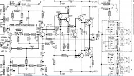
attached is a segment of the schematic i'm working off of:
thanks again,
Thanks in advance for your help here. I recently acquired a NAD 7020 amp and found that it had a dead channel. When i dug into it and probed around with my scope, i found that i had signs of audio all the way until the emitter of Q608. The base showed audio, the emitter had nothing.
I pulled the board out of the amp and saw that r644 was burnt up.
I replaced r644, powered the amp back up and quickly measured the voltage drop across it, and it's around 8 volts, putting the dissipation at a watt. I shut the amp off before it burnt out the next resistor.
I checked the values of the other resistors in this circuit and also compared to the working channel, and everything seems to check out. i checked the transistors with a multimeter too.
Clearly there's something causing the excessive draw on this side, but i'm not sure as to the best way to approach troubleshooting this as i'm a little new to the trade. I'd appreciate any guidance as to the best way to approach this problem.
attached is a segment of the schematic i'm working off of:
thanks again,
Attachments
Ah, it's this suicidal thing with no emitter resistors on the outputs again. Wonder how these even make it for so long. You wouldn't want any bad solder joints or bad thermal contact on Q610, that's for sure. On other similar models, people have added the customary 0.22 ohm / 3-5 W resistors that everybody else uses, and tweaked bias setting resistors to match. (The original NAD 3020 didn't have any because they used hometaxial 2N3055s, which basically come with some resistance built-in.)
Have you thoroughly checked Q612/614/616/618 with the diode test? I suspect that some of these may be shorted B-E.
Normally R644 current is set by ~25 V / (R628 + R650). Failing a shorted C626 (check), the only place the excess current could really go is the output stage.
Have you thoroughly checked Q612/614/616/618 with the diode test? I suspect that some of these may be shorted B-E.
Normally R644 current is set by ~25 V / (R628 + R650). Failing a shorted C626 (check), the only place the excess current could really go is the output stage.
Thanks for the reply. c626 is looking good, no short. I have checked all of those transistors with the diode setting from B-E and C-E except for q616 and q618. I'll pop them off the heatsink to be sure and report back.
the resistors are also checked out.
Do you think there could be an issue with a cracked solder joint or anything like that? I was really thinking there has to be a shorted component somewhere, i'm really surprised it's not more obvious from my meter. I'm almost wondering if i need to power this thing up and risk burning that resistor again to check voltage drop on components. Maybe something that is only shorting under power?
A dim bulb tester will help if you have a short / high current path. They are very simple to make and can be done for around $10.
I used a light switch with external mount box, an extension cord cut in half and a batten mount light fitting with a halogen bulb (globe), all mounted onto a piece of MDF. All the AC is safely enclosed and the switch is remote to the DUT.
I used a light switch with external mount box, an extension cord cut in half and a batten mount light fitting with a halogen bulb (globe), all mounted onto a piece of MDF. All the AC is safely enclosed and the switch is remote to the DUT.
You bring up a good point, I may use my variac to power this up at 60v instead... I'm only passing a watt over that resistor. it's not even enough to pop the fuse, but definitely enough to burn up the 1/4 watt resistor that's there.
I'm going to pop the power transistors off and make sure they're not shorted. I think i'm going to measure voltages between the L and R side after that to isolate this further. I'll try and run the radio on 60v and only keep it powered on for short periods of time while i test.
I'm going to pop the power transistors off and make sure they're not shorted. I think i'm going to measure voltages between the L and R side after that to isolate this further. I'll try and run the radio on 60v and only keep it powered on for short periods of time while i test.
Have you thoroughly checked Q612/614/616/618 with the diode test? I suspect that some of these may be shorted B-E.
Ah so q618 IS shorted base to emitter!!! Thank you so much for that tip.
I'm really trying to wrap my mind around the current flow with this failure. Would this short have been drawing all of that through R628, Q612, R652? I'd imagine replacing q612 and q614 would also be wise too...
On other similar models, people have added the customary 0.22 ohm / 3-5 W resistors that everybody else uses, and tweaked bias setting resistors to match.
I have to admit, i'm really new to amplifiers so a bit of this flew over my head. I learned about the built in resistance, there's a number of threads on that and the drawbacks of that design. do people add the .22 between the emitter of q616 and q618?
I'm also trying to wrap my mind around what resistors control the bias for this circuit. Again, just a hole in my understanding. There's a lot of transistors that are driving other transistors. I'm just failing to understand where a static DC bias voltage is applied.
I'm happy to do some reading as well if you could recommend a good resource or search keyword.
Thanks-
- Status
- This old topic is closed. If you want to reopen this topic, contact a moderator using the "Report Post" button.