Hello all,
I need some help identifying the problem with the ML No23 amplifier.
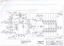
Left channel still works which is big help, but the right channel is broken. When the right channel broke I remember measuring 3v DC in the speaker terminals. In the attached schematic you can see the point after predriver where there should be + and -1.5v but for some reason both sides hit to the negative rail voltage around -80v. When I remove both unregulated VCCs I have 0v in the positive side and -3v in the negative side. If I remove the unreg VCCs from the working channel it keeps the + and -1.5v. I have already changed all the biggest caps from the board and the transistors Q25,26,23,27 because I suspected those. Transistors Q32-37 and Q44-49 are not connected. I have checked all the supply voltages and they are right. Any help is appreciated!
Br,
Handel
I need some help identifying the problem with the ML No23 amplifier.
Left channel still works which is big help, but the right channel is broken. When the right channel broke I remember measuring 3v DC in the speaker terminals. In the attached schematic you can see the point after predriver where there should be + and -1.5v but for some reason both sides hit to the negative rail voltage around -80v. When I remove both unregulated VCCs I have 0v in the positive side and -3v in the negative side. If I remove the unreg VCCs from the working channel it keeps the + and -1.5v. I have already changed all the biggest caps from the board and the transistors Q25,26,23,27 because I suspected those. Transistors Q32-37 and Q44-49 are not connected. I have checked all the supply voltages and they are right. Any help is appreciated!
Br,
Handel
Hi Handel,
Do I understand you correct that when the Amp went down you had +3Volt at the spkr output ?
In that case it's fully understandable that you measure -80Volt at WH.1 and WH.5 because the amplifier section at the left (up to Q26) tries to correct the positive output voltage by going completely down to -80Volt.
You mention to have disconnected Q32-37 and A44-49, meaning that the feedback point 'f' between R44 and R20 is only connected to R212, R122 (and the Zobel network R128 etc.).
Now what you have to do to check the amplifier part, is to connect WH.1 to WH.5 and connect this to point 'f'.
When applying power, this point, now acting as output, should go to zero volt.
I so, everything left from C42 seems to be working properly.
Let me know what you see, and we will make the next step.
Hans
Hello Patrick,
I have checked that area before and the values are same as in the left working channel. Now I will not touch that area because last time when measuring I made a short and broke a few components. ; )
Hans,
Correct, when the amp went down there was 3V in the speaker output.
I made the required connections and there is now zero(0.013V) in the output.
I cannot wait for the next steps!
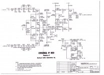
Here is the schematic of the OL-2 board where the WH.I and WH.5 are going. In these measurements WHs are not connected to OL2 board but left open. It is a separate PCB connected to the back of the amplifier whrere the input and speaker connectors are.
Could it be that the problem is here? Diodes?
Br,
Hannu
Could it be that the problem is here? Diodes?
Br,
Hannu
Attachments
Hans,
Correct, when the amp went down there was 3V in the speaker output.
I made the required connections and there is now zero(0.013V) in the output.
I cannot wait for the next steps!
Good to hear that so far everything is O.K.
Now four new steps still without the OL-2 Board.
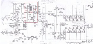
1: Connect WH.1 to 'f' and measure the voltage on WH.1 and WH.5 (resp ca. 0V and -3.6Volt)
2: Connect WH.5 to 'f' and measure WH.1 and WH.5 (resp ca. 3.6V and 0V)
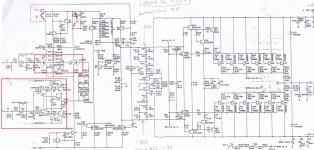
3: connect 'f' to the junction of R34 & R26 and measure the voltage at this point and on the junction of R9 & R1 (resp ca. 0V and -1.5 V)
4: connect 'f' to the junction of R9 & R1 and measure the voltage at this point and at the junction of R34 & R26 (resp ca. 0V and 1.5 V)
Then repeat the last two steps but now with the OL-2 board. This should make no difference for the voltages measured in 3) and 4).
Succes
Hans
Handel,
You have disconnected the TO3 output transistors, right ?
How did you do that, by taking them out ?
If so, if would be a good idea to test them with your universal meter in the diode test position.
From base to collector and from base to emitter you should see a diode in the right direction depending on NPN or PNP.
No short circuits or anything else should be the case.
Hans
Long time ago I had have the No 23.5 on the desk with similar issue, but on both channels. The reason therefore was't fix exactly, but after replace all the small electrolytics from main board and other parts like zeners from areas with thermal stress (e. g. LM394 dual small signal BjT) the amp works fine without any trouble.Hello all,
I need some help identifying the problem with the ML No23 amplifier.
Left channel still works which is big help, but the right channel is broken. When the right channel broke I remember measuring 3v DC in the speaker terminals. In the attached schematic you can see the point after predriver where there should be + and -1.5v but for some reason both sides hit to the negative rail voltage around -80v. When I remove both unregulated VCCs I have 0v in the positive side and -3v in the negative side. If I remove the unreg VCCs from the working channel it keeps the + and -1.5v. I have already changed all the biggest caps from the board and the transistors Q25,26,23,27 because I suspected those. Transistors Q32-37 and Q44-49 are not connected. I have checked all the supply voltages and they are right. Any help is appreciated!
Br,
Handel
If troubleshooting is necessary there are a good way to fix the reason for unwanted effects. Input stage, VAS-stage and output stage must be prepare for operating in an independent mode. Details therefore I have mentioned anywhere here on diyaudio.
Last edited:
Handel,
Here is already the next test in case all the above tests were o.k. including the testing of the TO3 output transistors.
Your amp should draw ca. 45 Watt in rest from the +/-86v unregulated power supply .
To test this, connect a 40 to 60 watt 230 volt light bulb between the 172Volt supply points and measure both voltages with respect to gnd.
When you have an oscilloscope at your disposal, you could also inspect the ripple on both voltages.
Hans
Last edited:
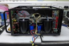
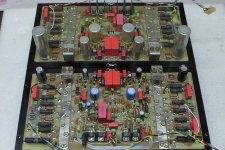
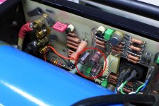
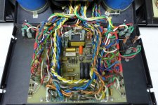
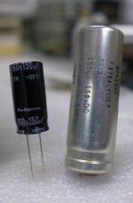
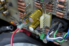
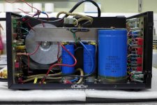
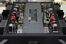
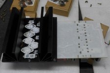
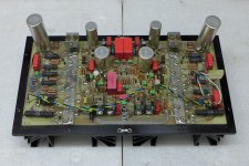
here a photo session of a replacement procedure:
After recap, inspect and reflow the... - Audio Tech Service Network | Facebook
Upload for saving the images is useful - so I think.
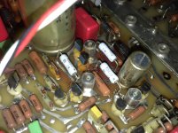
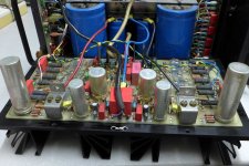
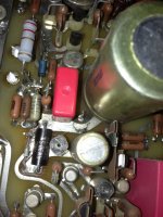
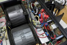
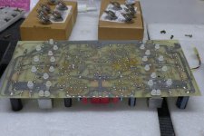
The main reason is the heating area on the main board from the first three images.
Definitely a misdesign by Mark Levinson in order of good reliability.
Why were the resistors not screwed onto the large heat sink in a version like under
MP9100-50.0-1% | Caddock Serie MP9100 Metallschicht-Lastwiderstand radial, 50Ω +-1% 100W | RS Components
https://de.rs-online.com/web/p/widerstande-durchsteckmontage/3778368/?relevancy-data=636F3D3126696E3D4931384E525353746F636B4E756D626572266C753D656E266D6D3D6D61746368616C6C26706D3D5E2828282872737C5253295B205D3F293F285C647B337D5B5C2D5C735D3F5C647B332C347D5B705061415D3F29297C283235285C647B387D7C5C647B317D5C2D5C647B377D2929292426706F3D3126736E3D592673723D2673743D52535F53544F434B5F4E554D4245522677633D4E4F4E45267573743D3337372D38333638267374613D3337373833363826&searchHistory=%7B"enabled"%3Atrue%7D
that is the question.
After recap, inspect and reflow the... - Audio Tech Service Network | Facebook
Upload for saving the images is useful - so I think.
The main reason is the heating area on the main board from the first three images.
Definitely a misdesign by Mark Levinson in order of good reliability.
Why were the resistors not screwed onto the large heat sink in a version like under
MP9100-50.0-1% | Caddock Serie MP9100 Metallschicht-Lastwiderstand radial, 50Ω +-1% 100W | RS Components
https://de.rs-online.com/web/p/widerstande-durchsteckmontage/3778368/?relevancy-data=636F3D3126696E3D4931384E525353746F636B4E756D626572266C753D656E266D6D3D6D61746368616C6C26706D3D5E2828282872737C5253295B205D3F293F285C647B337D5B5C2D5C735D3F5C647B332C347D5B705061415D3F29297C283235285C647B387D7C5C647B317D5C2D5C647B377D2929292426706F3D3126736E3D592673723D2673743D52535F53544F434B5F4E554D4245522677633D4E4F4E45267573743D3337372D38333638267374613D3337373833363826&searchHistory=%7B"enabled"%3Atrue%7D
that is the question.
Attachments
-
 Mark Levinson No 23-new caps-II.jpg98.2 KB · Views: 848
 -
 Mark Levinson No 23-PA main board.jpg127.7 KB · Views: 720
 -
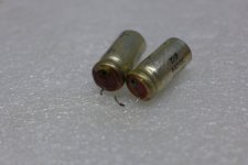
 Mark Levinson No 23-new caps-I.jpg91.3 KB · Views: 950
 -
 Mark Levinson No 23-hot-spot.jpg694.4 KB · Views: 837
 -
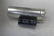
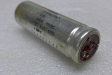 Mark Levinson No 23-faulty cap.jpg50.2 KB · Views: 832
 -
 Mark Levinson No 23-hot-spot caps.jpg45.7 KB · Views: 866
 -
 Mark Levinson No 23-III.jpg110.8 KB · Views: 690
 -
 Mark Levinson No 23-II.jpg119.6 KB · Views: 603
 -
 Mark Levinson No 23-I.jpg127.6 KB · Views: 975
 -
 Mark Levinson No 23-I-I.jpg562.7 KB · Views: 634
Last edited:
more pictures
Attachments
-
 Mark Levinson No 23-VII.jpg54.5 KB · Views: 410
 -
 Mark Levinson No 23-IX.jpg87.1 KB · Views: 441
 -
 Mark Levinson No 23-X.jpg97.5 KB · Views: 447
 -
 Mark Levinson No 23-XI.jpg98.2 KB · Views: 907
 -
 Mark Levinson No 23-XII.jpg118.3 KB · Views: 516
 -
 Mark Levinson No 23-XIII.jpg98.6 KB · Views: 447
 -
 Mark Levinson No 23-XIV.jpg122 KB · Views: 486
 -
 Mark Levinson No 23-XVII.jpg91.2 KB · Views: 476
 -
 Mark Levinson No 23-XVIII.jpg70.8 KB · Views: 460
 -
 Mark Levinson No 23-VI.jpg66.1 KB · Views: 404
Last edited:
Hello Hans,
Here are the results:
Step 1. 0V and -2.8V works.
Step 2. 2.8V and 0V works.
Step 3. 0V and 0V ?????
Step 4. 0V and 0V ?????
Question: Should I connect also VCC unregs because in these tests I have not connected VCC unregs? Everything from beginning?
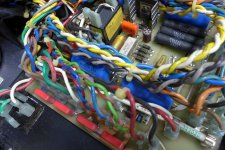
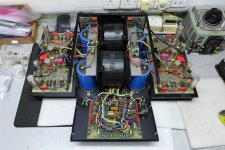
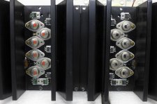
The transistors Q32-Q42 and Q44-Q29 I have desoldered because it is impossible to do soldering when those are connected. I want to be as sure as possible that amp works totally before I solder those back. It can easily be seen from the pictures. Thanks tiefbassuebertr!
Here are the results:
Step 1. 0V and -2.8V works.
Step 2. 2.8V and 0V works.
Step 3. 0V and 0V ?????
Step 4. 0V and 0V ?????
Question: Should I connect also VCC unregs because in these tests I have not connected VCC unregs? Everything from beginning?
The transistors Q32-Q42 and Q44-Q29 I have desoldered because it is impossible to do soldering when those are connected. I want to be as sure as possible that amp works totally before I solder those back. It can easily be seen from the pictures. Thanks tiefbassuebertr!
last images.
check out for additional information
https://www.diyaudio.com/forums/solid-state/92311-mark-levinson-23-a.html#post6142303
need some help on my Mark Levinson No23
check out for additional information
https://www.diyaudio.com/forums/solid-state/92311-mark-levinson-23-a.html#post6142303
need some help on my Mark Levinson No23
Attachments
Last edited:
So, I repeated all the measurements so far with VCC unreg connected and the results were exactly same. The question is, what happens in the steps 3 and 4?
Transistors Q38, 40, 30, 29 and 50, 52, 41, 42 are connected.
Yes, my assumption was that VCC unreg was still connected, which is what you did now.
That you measure 0V and 0V in steps 3) and 4), means that no current is flowing in R50, where it should be some 35mA, giving a voltage drop over R50 of 1.5Volt.
That can only mean that something is broken here.
You should go back one step by connecting 'f' again to WH.1 an check wether there is a current flowing through R45 (ca 15mA)
If no current is flowing here, it points in the direction that Q40 and Q52 are broken, or that R36 and R13 are burned.
When however there is some 15mA current flowing trough R45, then check R25 to R28 and R1 to R4 and also R34 and R9. This can all be done in circuit.
Measured values do not have to be exact, but just see wether these resistors are not open or short circuited.
When they are alright, you will have to check Q29, Q30, Q41 and Q42.
But before you continue, could you please first do the test with the 40-60Watt 230V light bulb between the 172V unregulated supply and measure their voltages and ripple with respect to gnd, so we know that there is nothing wrong here.
Hans.
- Home
- Amplifiers
- Solid State
- Mark Levinson No23 repair help