Is it so that with the pot I should be able to change the idle current of the output transistors?
Yes, that’s the sole function of this pot.
Hans
I don’t understand your calculation of idle current.I measured the voltage in the output and that is 17.5mV. Idle current is only 50mA. Voltage over R20 and R44 is 34mV.
When you meaure 34mV over 2*0R1, current is 170mA, right ?
Or was it 34mV per resistor, in that case idle current is 340mV, both quite close to the 275mA thar ML specifies.
So your Left Amp seems to be working perfectly as a reference.
Just turn the pot a bit to get the 55mV over the combined R20 and R44, look in the sim that I sent you.
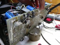
Great, did you already test them ?I have unsoldered 12 output transistors and taken them out.
And have you solved the power supply problem over the pre-drivers ?
So what is your current status.
Hans
34mV per resistor, same value in both R44 and R20. I remeasured over both resistors and I get 75mV. I have not yet tested the output transistors. Some time ago I went them quickly through and at least there were no shorts.
I still have the problem in the pre-drivers. I just cannot find any broken components in that "2) R9/R34, R26/R27, R1/R4, R36/R13, R25/R28, R2/R3 and last but not least Q29/Q30, Q41/Q42" area.
How can this part work if Q40, 29, 30 are not connected to the VCC unreg? Do I need the output transistor from now on?
34mV per resistor, same value in both R44 and R20. I remeasured over both resistors and I get 75mV. I have not yet tested the output transistors. Some time ago I went them quickly through and at least there were no shorts.
I still have the problem in the pre-drivers. I just cannot find any broken components in that "2) R9/R34, R26/R27, R1/R4, R36/R13, R25/R28, R2/R3 and last but not least Q29/Q30, Q41/Q42" area.
How can this part work if Q40, 29, 30 are not connected to the VCC unreg? Do I need the output transistor from now on?
Look at the sim, the pre-drivers can’t work without power supply at their collectors.
Also look and measure at the left channel and try to find out how this supply is provided. Could be a wire but also through a pcb trace that is burnt.
But now matter how, you will need the unreg power supply at their collectors.
Hans
Now I got it. Collectors are connected through the PCB and transistors with the screws to the VCC unreg!!! I have just soldered the two pins of the transistors(Q40,29,30)without the screws which means no VCC unreg. These three transistors are connected normally to the big heatsink but now I do not have it. Tomorrow I will connect also the collectors to VCC unreg and lets see what happens.
That’s o.k., after warming up it will go to 15.8mA.
But this means that potmeter R124 now should be adjusted.
So with ‘f’ still connected to WH.1 connect your multimeter over R50 and turn the pot until you have ca. 1 Volt over R50.
After that please tell me the voltage on WH.5
Hans
Hello Hans,
Now the VCC unreg is connected to the transistors Q40, 29, 30 and Q52, 41, 42. I powered the amp without feedback connected to the predriver but I still had the negative rail voltage(-80V) in the predriver. I did again the step above and I was able to change the voltage over R50. Now the voltage over R50 is 1.3V and in the WH.5 I have -3.6V.
Ah, that's great to hear. It means that everything so far is now 100% working properly.
1.3 Volt on R50 is a bit too much to start with, so try to bring this to 1 Volt with pot R124.
The next and the last step is to mount the TO3 output transistors after having disconnected 'f' from WH.1.
You don't have to install them all in one go, but you could start with one complementary pair that you have tested in advance.
With one pair installed, turn R124 until no more than 50mA is flowing through R20 and R44, or 10mV over both and measure the output voltage 'f'.
When this is o.k., you can mount the other TO.3's pair by pair or just all in one go, but be sure they are tested properly in advance before mounting.
Hans
Handel,
You are making progress!
Are your output modules physically separated from the chassis but connected electrically while you are taking your measurements? On my No. 27, there is so little room to insert probes I am unsure how to take measurements while the modules are screwed onto the chassis. Separating them poses problems because of how the main caps are attached. Would you mind posting some photos of your amp in its current state? I know the 23 is different, but I am curious.
Thanks!
Sorry, GKTAUDIO I will come to your questions a bit later.
Hans,
I soldered one pair of output transistors and powered the amp, and do you know what, I have + and - 1.6 Volts in the predriver!!!
Do you need other mesurements to verify the operation before I solder rest of the output transistors and the heatsinks?
Hans,
I soldered one pair of output transistors and powered the amp, and do you know what, I have + and - 1.6 Volts in the predriver!!!
Do you need other mesurements to verify the operation before I solder rest of the output transistors and the heatsinks?
Before soldering the two output transistors, I adjusted 1V over R50. After soldering the two output transistors I adjusted the voltage over both R20 and R44. It is very hard to turn the pot while the amp is on so I need to switch of the amp and then do the tuning. In some point of the tuning process the voltage over R20 and R44 jumped to 50mV but I quickly turned the amp off. Now if I tune the voltage to about a few millivolts it is not steady anymore. The voltage starts to increase closer to 10mV and in some point amp switches itself off. Did I broke something ?
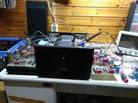
OMG, what a mix of boards and cables.
I was not aware that the drivers and output transistors were not yet connected to the heatsink.
This will cause a very rapid thermal runaway.
But no problem, your amp probably switched of because the DC output voltage went above a certain value or it even started oscillating.
So if you want to test without heatsink, turn the pot back in its maximum value of 500 Ohm and turn on the amp.
Then turn the pot while measuring on R50 until you have ca 600mV.
In the meantime, the output voltage should stay within 25mV.
Let me know how this goes.
Hans
Hi Handel,
Since everything worked fine without the output pair, I think it might be better to go back to the last step without the TO3’s but now with the pre-drivers mounted on the heatsink.
With ‘f’ connected to WH.1 you should again set 1Volt on R50.
When that’s o.k. mount the first complementary output pair and test again as you did without heat sink.
Since nothing was broken so far, my current feeling is that the original cause of your problem was that the collectors of the lower pre-drivers where making a bad contact to the negative unreg supply. That’s the only thing that seems to make sense.
Hans
Hello Hans,
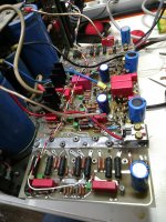
The pre driver transistors Q23, 25, 28, 26 are already in in the small heat sinks(you can see it in the middle photo, heat sinks are standing high from the PCB). Transistors that belong to the 2 big heat sinks are 12 output transistors, Q40, 29, 30 and Q52, 41, 42 + two transistors from the voltage regulator, which cannot be seen from the schematic. It will be hard to solder transistors partly to the big heatsinks, I rather solder all them in one go.
So what should measure/tune, before soldering the rest transistors to the heatsinks? I want to be sure that everything works before that.
I have tested all the output transistors and they work.
- Home
- Amplifiers
- Solid State
- Mark Levinson No23 repair help