Hi,
I've been a long time reader of the forums but this is my first post here.
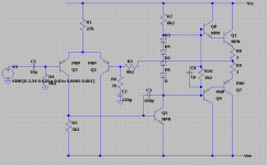
I'm currently building a headphone amplifier for guitar. This is my circuit at the moment:
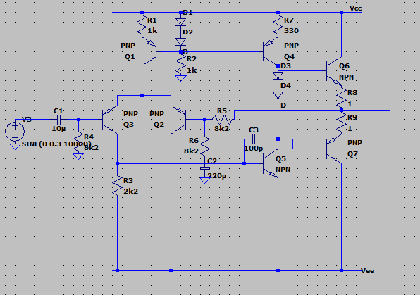
All transistors are MPSA42/92 except for the output pair which are TIP31C/32C. The diodes are all 1N4148. The power rails are +-15V
The amp can drive a pair of headphones and sounds clean with a guitar plugged in (via a TL071 buffer). However, on fast, loud transients, I get a popping sound. When viewed on an oscilloscope, the output is jumping suddenly to around -15V, showing a narrow, square pulse.
I'm not sure what is causing this. Any ideas?
Thanks in advance!
James
I've been a long time reader of the forums but this is my first post here.
I'm currently building a headphone amplifier for guitar. This is my circuit at the moment:
All transistors are MPSA42/92 except for the output pair which are TIP31C/32C. The diodes are all 1N4148. The power rails are +-15V
The amp can drive a pair of headphones and sounds clean with a guitar plugged in (via a TL071 buffer). However, on fast, loud transients, I get a popping sound. When viewed on an oscilloscope, the output is jumping suddenly to around -15V, showing a narrow, square pulse.
I'm not sure what is causing this. Any ideas?
Thanks in advance!
James
Attachments
I suspect the issues are caused by the very high feedback factor that is causing stability and latching issues. The gain is only 6db which is extremely low.
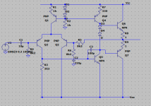
As a very quick test try adding a 1k (or even a bit lower) between the bases of Q2 and Q3 and see if that improves things. It might give us a clue.
As a very quick test try adding a 1k (or even a bit lower) between the bases of Q2 and Q3 and see if that improves things. It might give us a clue.
Attachments
Thanks for the replies! I've scoped both power rails and nothing is happening when it latches up. I've tried the resistor between the bases on the LTP and also increasing the gain by swapping R6 for 1k. Neither has made an improvement unfortunately.
If it helps, according to my PSU, it's drawing 23mA from the +ve supply and 9mA from the -ve with the input grounded.
Thanks,
James
If it helps, according to my PSU, it's drawing 23mA from the +ve supply and 9mA from the -ve with the input grounded.
Thanks,
James
Stupid question - are you absolutely sure you can rule out the TL071 as the source of your issues? These chips (and some others) are notorious for phase inversion when hitting their common-mode input voltage limits, and if you were supplying this one with a 9 V battery I would imagine you could hit those quite easily with an electric guitar, as you need to keep away almost 3 V from V-...
I am not exactly sure what you are hoping to gain with an all-discrete circuit as opposed to the same output stage (buffer) on a garden variety opamp (4580, 5532, whatever). Output current is probably limited by the lowish VAS current (I don't think TIP31/32C beta is terribly high?), not to mention the bias diodes could use a speedup capacitor in parallel for improved symmetry in the high-frequency regions.
I am not exactly sure what you are hoping to gain with an all-discrete circuit as opposed to the same output stage (buffer) on a garden variety opamp (4580, 5532, whatever). Output current is probably limited by the lowish VAS current (I don't think TIP31/32C beta is terribly high?), not to mention the bias diodes could use a speedup capacitor in parallel for improved symmetry in the high-frequency regions.
Although probably not related, R2 is very low in value and pulling a relatively high current compared to what is needed. Something like an 8k2 might be more appropriate.
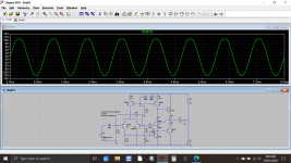
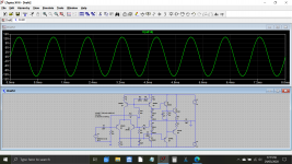
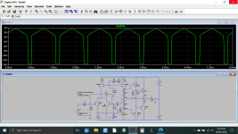
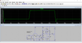
@sgrossklass looks correct with suspecting the low gain TIP devices. I've just tried a quick sim.
This is with a 32 ohm load. If we change the outputs for something with a little higher gain we get this.
Also (fwiw) the simulation with TIP devices comes in at 24 and 10ma current draw.
@sgrossklass looks correct with suspecting the low gain TIP devices. I've just tried a quick sim.
This is with a 32 ohm load. If we change the outputs for something with a little higher gain we get this.
Also (fwiw) the simulation with TIP devices comes in at 24 and 10ma current draw.
Attachments
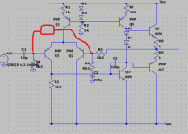
One thing that might be worth doing is putting a 1K base stopper resistor at Q4. If the VAS Q5 is driven into saturation, Q4 can severely load the voltage reference formed by D1 D2, which in turn affects the LTP current source Q1.
As you are only driving headphones, BD139/BD140 is a better choice for output resistors.. or if you want a little extra edge, MJE243/MJE253.
As you are only driving headphones, BD139/BD140 is a better choice for output resistors.. or if you want a little extra edge, MJE243/MJE253.
Hi,
I've had a chance to fiddle around with it a bit more now.
I've scoped the output of the TL071 and there's no clipping going on. It's powered from the +-15V rails.
I've replaced R2 with an 8k2 now. I tried adding the base stopper resistor to the VAS current source but it didn't help. I scoped the voltage reference to the current sources and it's remaining stable the whole time.
The TIP31/32 are the only sensibly sized power transistors I have to hand at the moment so I added a pair of driver transistors (MPSA42/92) with a 1u speedup capacitor across the resistor between their bases to try and increase the current gain in the output stage. I added an extra two bias diodes to account for the additional voltage drop.
I also tried adding an emitter follower to the VAS in case it was that being overloaded but it made no difference so I changed it back.
Unfortunately, none of these changes have made a difference so far. When driving low impedance headphones, it is more than loud enough well before it is turned up enough to induce the clipping so it's not a problem. Driving 400ohm headphone though, it needs to be turned up into that region.
In terms of why I'm trying to build an all-discrete amp instead of just adding an output stage to a 5534, it's mainly just for fun, the challenge and the learning experience. I'm currently shut up in my house for what will probably be a while and it seemed like a good project. I am going to use a buffered op-amp for the reverb driver circuit when I get onto that (assuming I can get the power amp working first!)
Thanks again for your help!
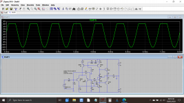
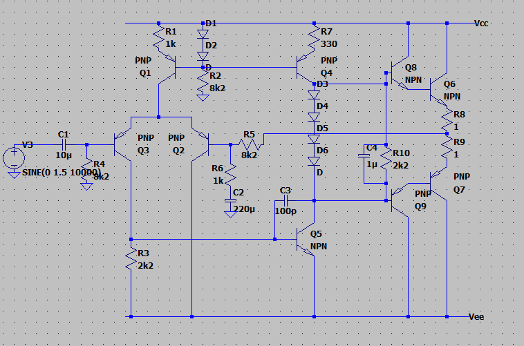
Here is my updated schematic and a scope trace to show what it's doing:

Thanks,
James
I've had a chance to fiddle around with it a bit more now.
I've scoped the output of the TL071 and there's no clipping going on. It's powered from the +-15V rails.
I've replaced R2 with an 8k2 now. I tried adding the base stopper resistor to the VAS current source but it didn't help. I scoped the voltage reference to the current sources and it's remaining stable the whole time.
The TIP31/32 are the only sensibly sized power transistors I have to hand at the moment so I added a pair of driver transistors (MPSA42/92) with a 1u speedup capacitor across the resistor between their bases to try and increase the current gain in the output stage. I added an extra two bias diodes to account for the additional voltage drop.
I also tried adding an emitter follower to the VAS in case it was that being overloaded but it made no difference so I changed it back.
Unfortunately, none of these changes have made a difference so far. When driving low impedance headphones, it is more than loud enough well before it is turned up enough to induce the clipping so it's not a problem. Driving 400ohm headphone though, it needs to be turned up into that region.
In terms of why I'm trying to build an all-discrete amp instead of just adding an output stage to a 5534, it's mainly just for fun, the challenge and the learning experience. I'm currently shut up in my house for what will probably be a while and it seemed like a good project. I am going to use a buffered op-amp for the reverb driver circuit when I get onto that (assuming I can get the power amp working first!)
Thanks again for your help!
Here is my updated schematic and a scope trace to show what it's doing:
Thanks,
James
Attachments
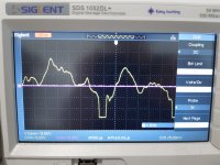
So... those driver transistors absolutely transform the current delivery. The amp can now sustain output into 4 ohm load at nearly -/+10 volts pk/pk. 400 ohm loading and its around -/+13 volts pk/pk.
If the scope shot is 5 volts per division then you are getting close to clipping and tbh you may find the 15 volt rails a limitation for driving the high impedance 'phones.
Its also worth checking the physical layout and grounding and load returns although 400 ohm loading shouldn't be inducing significant current related volt drops (that can cause weird behaviour if they cause positive feedback) anywhere.
Attachments
I'll have another play with it tomorrow and double check all the connections to the transistors. It's getting pretty spaghettified now so I may just rebuild it a bit neater so I can see what I'm doing a bit better.
I do have decoupling on the rails. I forgot it initially but it doesn't seem to have made a difference.
Thanks again,
James
I do have decoupling on the rails. I forgot it initially but it doesn't seem to have made a difference.
Thanks again,
James
I couldn't resist having a look at it now and I've found the problem! I had the collector of Q2 connected to ground instead of Vee!
I just have a bit of normal clipping now when driving the 400ohm headphones but there's nothing to be done about that. Increasing the rails to 18V gives a bit more but I can't take it any higher or I'll fry the op amps.
Time to move onto the preamp now I think!
Thanks,
James
I just have a bit of normal clipping now when driving the 400ohm headphones but there's nothing to be done about that. Increasing the rails to 18V gives a bit more but I can't take it any higher or I'll fry the op amps.
Time to move onto the preamp now I think!
Thanks,
James
Excellent. That's quite an interesting scenario and as Mark mentioned, the NFB does a pretty good job trying to keep it all together 
The opamps don't need run on the full supply because the power amp stage also has voltage gain. You can use a simple resistor/Zener shunt for each opamp rail and go as high as you like with the supply.
The opamps don't need run on the full supply because the power amp stage also has voltage gain. You can use a simple resistor/Zener shunt for each opamp rail and go as high as you like with the supply.
Attachments
Hi,
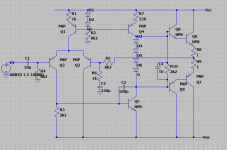
I decided to simplify the circuit a bit and replaced the current sources with fixed resistors.
I've now been doing some measurements and have calculated a slew-rate of 0.18V/uS which seems pretty bad. The slew-rate is the same whether I have the current source version or the simplified version.
Any ideas on where to start to improve it or is this sort of slew-rate just standard for a design like this?
Thanks,
James
Attachments
Right, I've had some time to do some testing and tweak the circuit. I've settled on the simpler version now.
Input grounded:
Input pair tail current = 0.53mA
Current through Q3 collector = 0.27mA
I had to adjust the value Q3's collector resistor to 2k2 to try and get the two currents equal. I'm pretty happy with getting it to 0.53 and 0.27. The adjustment also improved slew rate.
Quiescent current (after 10 min switch on) = 6.4mA
VAS current = 0.76mA
DC offset <2mV (I'm not sure why it's so good!)
Saturates at +-13.5V with no load
Slew rate (no load) = 2.5 V/uS
Slew rate (20ohm load) = 2.2 V/uS
Assuming that we need around 40mW power output for headphones, and using 20kHz max frequency and 32ohm load, I calculated the required slew rate to be 0.142 V/uS.
All in all, unless I've made some terrible mistakes (feel free to point out), and although I've only made basic measurements, I'm pretty pleased with the amp's performance. It seems to be up to the job now.
These measurements were all taken on the actual amp, not the simulation. In terms of the correct transistor models, I haven't used LTSpice for a while and I suppose I've got a bit lazy! I sort of relearning it and need to remind myself of how to import the .MODEL statements.
Thanks,
James
- Status
- This old topic is closed. If you want to reopen this topic, contact a moderator using the "Report Post" button.
- Home
- Amplifiers
- Solid State
- Headphone amp build