Hi oldjack,
As a suggestion, from what I see of your mechanical constraints, it is possible to use the BC-1 AFE(Amplifier front end), that I designed, mount it on the heatsink and just do another small OPS(output stage) pcb which would be pretty small and simple if it only contains 4 transistors(bjts). The AFE that I did is 100x100mm, I am not sure how high your heatsinks are. The performance would be remarkable with as I can atest to when I did the listening evaluation of the simple design.
You do not have to make the OPS as complicated as the one I did, since it incorporates the protection circuitry, 2 pairs of output bjts.
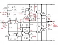
I am not sure why your design does not show a inductor/resistor and if you are okay which not having any protection circuitry, delayed turn on etc.
Rick
As a suggestion, from what I see of your mechanical constraints, it is possible to use the BC-1 AFE(Amplifier front end), that I designed, mount it on the heatsink and just do another small OPS(output stage) pcb which would be pretty small and simple if it only contains 4 transistors(bjts). The AFE that I did is 100x100mm, I am not sure how high your heatsinks are. The performance would be remarkable with as I can atest to when I did the listening evaluation of the simple design.
You do not have to make the OPS as complicated as the one I did, since it incorporates the protection circuitry, 2 pairs of output bjts.
I am not sure why your design does not show a inductor/resistor and if you are okay which not having any protection circuitry, delayed turn on etc.
Rick
Last edited:
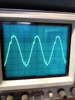
Hi Patrick, I first fitted the 8pf cap which seemed to cause some oscillation.
Then I fitted the two 220pf caps. This stopped the oscillation when connected to a speaker 6ohm load.
I get a nice sine wave output when connected to a load.
I will do the remaining mods as you suggest tomorrow but it looks like the 220pf caps have made the difference.
The second amplifier channel is faulty as voltage readings across the board are all high negative values.
Yes, the 220pf caps are very important, so that I suggested first in #17
https://www.diyaudio.com/forums/solid-state/351771-parasitic-oscillation-2.html#post6136684
The others caps just to make the amp more stable as kind of compensation.
For your second amp channel output all negative supply voltage, maybe the wrong PCB layout or misplaced transistor in the positive supply rail side.
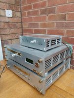
Hi Rick, have attached photo of my triamp, the small top unit houses the speaker protection circuits, need a total of 6 separate units as there are no cross overs to the speakers. The top cabinet houses the filter, amps, attenuator, controls, small power supplies, and is completely full so there is no available space. HT is 60mm but I will be putting the speaker protection board on top of the filter. I also have an earth collection PCB with over 30 connections, this reduces to 3 main earth wires to the power supply unit. So it is a major job to find any space. It's my own fault for building such a complicated audio system. But I do thank you for being so generous. I would like eventually to build another triamp perhaps using three of the BC amps, that would be a great system.
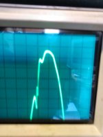
Have done the modifications to the amps and although stable the waveform is poor. It is the same from both channels. Attached picture is the sine wave output at 5khz.
Any ideas on what is causing this
Any ideas on what is causing this
Attachments
The schematic is as your marked up version. I found a short across Q4 on the faulty channel so both channels now operate.
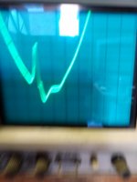
When I had a nice sine wave I was testing with a 100hz input signal and the sine wave looked good except there were slight gaps in the waveform which when magnified showed a small distortion. But when I increased the frequency I got the distorted waveform as in the photos.
When I had a nice sine wave I was testing with a 100hz input signal and the sine wave looked good except there were slight gaps in the waveform which when magnified showed a small distortion. But when I increased the frequency I got the distorted waveform as in the photos.
Have done the modifications to the amps and although stable the waveform is poor. It is the same from both channels. Attached picture is the sine wave output at 5khz.
Any ideas on what is causing this
first make sure your bias voltage(R18 value) is correct set for the amp so that the output power transistors has suitable bias.
second you check again each stage current is run correctly as the schematic
you have scope so that it is more easy for you to measure each stage curve and find out which stage has this problem.
What is your amp's operating voltage, if it is like +-35V then you may simplify your amp with less stage.
Have checked some readings this morning.
Q5 collector 0.5v
Q5 base -1.08v
Q5 emmitter -1.77v
So does this mean R8 is wrong.
Supply voltage is +/- 30v (this is a temporary supply, actual will be +/-35v)
Osc trace yesterday was 10v wave ht (20v peak to peak)
Load is 8R resistive
On the output I have a RC to ground, 10R resistor with 100n cap in series.
For the bias voltages on q16 and q17 which should be +1.84v and -1.84v, mine is +0.54v and -1.77v.
If the one is correct how do I adjust the other.
Will do some more readings today.
I guess it's my own fault that I did not fit a variable resistor for R8, always have done on other amps, it's very tight for space around these resistors so I am thinking that hopefully when I sort this amp out I will do a new PCB and try and reuse the components. It's just that I am limited for space in the triamp case.
For the bias voltages on q16 and q17 which should be +1.84v and -1.84v, mine is +0.54v and -1.77v.
Your bias voltage is definitely not enough for your amp, so that it output with distortion, to avoid distortion the "output power transistors must at least have 30mA bias current", so that you measure between both "power transistor's emmitter must have a 20mv reading(if your emmitter resistors is 0.33R)".
To get the correct bias voltage, you have change R8, you fixed R7 value and only change R8, you can calculate R8 as below (all resistor values in ohm)
Bias voltage,"you need total 3.62v" = 0.6 + (0.6/R7)*R8
You need to fine tune(R8) the bias voltage so that both transistors have enough bias current.
Do you add the 220uF cap to resistor R2 ?
Attachments
Last edited:
The R-L on the output effectively decouples from the capacitance of the speaker leads (we're talking about high frequencies here) in order to maintain Nyquist (frequency) stability - which hopefully is achieved using an adequate pole in the forward path (the 30pF - or more - Miller capacitor).
In fact, there's dual reason for the decoupling of the output - and that is to isolate the emitters from the capacitance presented by the speaker leads. (Emitter-followers hate load capacitance - they tend to oscillate. Hence the practice of base-stopper resistors - another recommendation.)
Hope all that helps!
Hi Patrick
I already had the capacitors between R2 and the.
I managed to fit variable resistor in place of R8.
Some readings I took
R8. 2.2k
Q5c 1.8v
Q4c. -1.8v
Q10e. 75mv
Q11e. -152mv
Good sine wave but heatsink gets very hot in short time.
R8. 1.9k
Q5c 1.5v
Q4c. -1.7v
Q10e. 46mv
Q11e. -50mv
Good sine wave and heatsink stable
Any ideas why the heatsink gets so hot.
Output connected to 8r speaker, also tried 8r resistive load with same results.
Can Q10e and Q11e voltages be reduced any further.
power transistor's emmitter must have a 20mv reading, measure between both power transistor's emmitter
the "output power transistors must at least have 30mA bias current", so that you measure between both "power transistor's emmitter must have a 20mv reading(if your emmitter resistors is 0.33R)
the "output power transistors must at least have 30mA bias current", so that you measure between both "power transistor's emmitter must have a 20mv reading(if your emmitter resistors is 0.33R)
- Status
- This old topic is closed. If you want to reopen this topic, contact a moderator using the "Report Post" button.
- Home
- Amplifiers
- Solid State
- Parasitic Oscillation