I looked at picture 3.10 in the book (1st edition) and the schematic is what Patrick posted in post #17. This is not a 'ready to build' amp. It is for illustrative purposes on a sequence of improvements Bob was showcasing in the chapter.
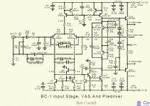
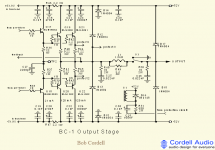
The amp is missing a lot of components, so I am not surprised it did not work. For a 'Bob Cordell' ready to build amp, look at the amp he presented at Burning amp:
Linear Systems
It is called the BC-1. The full schematic is on the PowerPoint.
Best, Sandro
The amp is missing a lot of components, so I am not surprised it did not work. For a 'Bob Cordell' ready to build amp, look at the amp he presented at Burning amp:
Linear Systems
It is called the BC-1. The full schematic is on the PowerPoint.
Best, Sandro
Thanks Sandro, I see what you mean, its a different amp to the one I made.
I only wanted this for a replacement base amp for my triamp, it is not that critical.
I made my triamp 3 years ago and it sounds great but I am thinking that if the base amp goes faulty I cannot replace it with the same item hence this unit.
I did make another base amp which is good but I thought this one might be better.
But I will try the mods suggested by Patrick first before giving up on it.
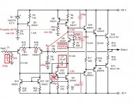
If you are using Q12 you need Q13 or a resistor in Q12’s collector. If you have neither you can get bad clipping behavior.
Adding decoupling to the rails, near the output transistors, will often cure load dependent oscillation. Adding the 5 to 10 pF cap from the VAS output to the summing junction is usually a good idea in circuits with a high open loop gain. Anything where you add another stage besides the usual diff pair./VAS almost always requires it.
Adding decoupling to the rails, near the output transistors, will often cure load dependent oscillation. Adding the 5 to 10 pF cap from the VAS output to the summing junction is usually a good idea in circuits with a high open loop gain. Anything where you add another stage besides the usual diff pair./VAS almost always requires it.
Amp clipping due to high input level.
The amp is going to full output and then it will clipping if more higher level input.
Sorry after checked my last built amp, I make the correction for the schematic in #19
https://www.diyaudio.com/forums/solid-state/351771-parasitic-oscillation-2.html#post6136710
Cap C1 30p original position is correct and at the input there is a 220p cap.
https://www.diyaudio.com/forums/solid-state/351771-parasitic-oscillation-2.html#post6136710
Cap C1 30p original position is correct and at the input there is a 220p cap.
Attachments
Hi Patrick, I first fitted the 8pf cap which seemed to cause some oscillation.
Then I fitted the two 220pf caps. This stopped the oscillation when connected to a speaker 6ohm load.
I get a nice sine wave output when connected to a load.
I will do the remaining mods as you suggest tomorrow but it looks like the 220pf caps have made the difference.
The second amplifier channel is faulty as voltage readings across the board are all high negative values.
Hi oldjack,
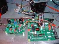
I am not sure if I can help you or not but I did work with Bob Cordell as I did do a layout of the BC-1 design that he presented at BAF. It was done in two boards. I have a few extra boards if you want them just PM me. All I ask is a small donation and pay for the shipping.
The AFE schematic is shown here which is for the pcb on the left. The deign is complete, fulled tested and characterized but there are mechanical challenges involved in packaging it in the current configuration. Bob would like me to do a new layout so that the design can be used in a DIYAudio chassis, I am contemplating that.
Attachments
Last edited:
")
Hi Rsavas, that's some circuit, I don't think mine will ever get to that stage.
Thanks for the offer, very kind of you, but as mine is a replacement for my existing triamp base unit I have to stay with the limited space to fit it in.
Even fitting some of the mods that Patrick recommended has removed the oscillation.
But I am sure that even the amp I have built will sound great in the triamp.
If I can get it to a reasonable level I would consider using it for all three amps in the triamp, it depends how much space I have got.
- Status
- This old topic is closed. If you want to reopen this topic, contact a moderator using the "Report Post" button.
- Home
- Amplifiers
- Solid State
- Parasitic Oscillation