It's been a while since I posted something... Since I build a tiny O2 headphone amp back in the day.
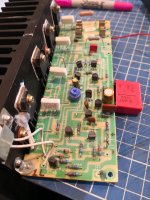
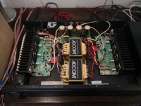
Cutting to the point since I got my paws over a decent Gfa535 the first thing as man's nature dictates is to open it up and mess with the guts.
Simple beast with a few caps to be changed /upgraded. That is done and out the way.
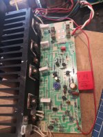
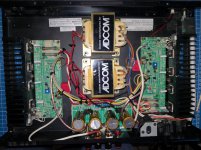
Next step is to change big caps in the power supply... and then I realized something seems odd, even though it's a dual mono with mirror boards I noticed one (L) has and extra cable that runs to the power supply.
I'M a newB but there is something the way the grounds are done that seems confusing and TBH I can't quite comprehend the why's and if there is a way to improve it.
I searched the forums and the only thing I found is a guy that sells a new PS board... But what can I DIY? .. In the case there is room for some improvement in the grounding section.
NUTSHELL
1. Recap - pretty much done
2. New inputs - In process
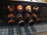
3. Speaker terminal replacement (speaker selector is being erased plus new 5 way binding posts to come)
4. Q607 will be eliminated from the L+R boards. According to my Guru (dad which is/was and everyday DYIaudio member that actually read pretty much all the posts in the Blowtorch thread LOL) that Q607 gets in the way of the overall circuit just to flash some clipping leads. I don't prefer LEDs over sound quality.
Some pics for mere reference and schematic added.
Any input and comments welcomed!
Cheers from Mexico,
ROB.
Cutting to the point since I got my paws over a decent Gfa535 the first thing as man's nature dictates is to open it up and mess with the guts.
Simple beast with a few caps to be changed /upgraded. That is done and out the way.
Next step is to change big caps in the power supply... and then I realized something seems odd, even though it's a dual mono with mirror boards I noticed one (L) has and extra cable that runs to the power supply.
I'M a newB but there is something the way the grounds are done that seems confusing and TBH I can't quite comprehend the why's and if there is a way to improve it.
I searched the forums and the only thing I found is a guy that sells a new PS board... But what can I DIY? .. In the case there is room for some improvement in the grounding section.
NUTSHELL
1. Recap - pretty much done
2. New inputs - In process
3. Speaker terminal replacement (speaker selector is being erased plus new 5 way binding posts to come)
4. Q607 will be eliminated from the L+R boards. According to my Guru (dad which is/was and everyday DYIaudio member that actually read pretty much all the posts in the Blowtorch thread LOL) that Q607 gets in the way of the overall circuit just to flash some clipping leads. I don't prefer LEDs over sound quality.
Some pics for mere reference and schematic added.
Any input and comments welcomed!
Cheers from Mexico,
ROB.
Attachments
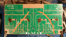
Yes indeed, the grounding on the 535 MK1 is confusing because it doesn't make sense! Nearest I can figure, they botched the design of the power supply board, but had already ordered mass quantities of boards, and so applied a factory bodge to make it work. You'll notice the wire for the signal ground is missing on the right channel. This point is meant to go to star-ground of the amp. You can see where they goofed on the original board. The points marked "E2" seem to be meant for these signal ground points from both channels to connect, and points "E" and "E1" for the zobel ground. However, between these points also flows return currents from the bypass capacitors, and so those points would not be "quiet" anymore, they are pulsating with capacitor charging currents, creating a delta between the signal ground and zobel ground, which is picked up by the feedback network.

The factory bodge ties the right channel's input ground reference to the left channel via the very long shield of the input wires. It's only partially effective.
I wrote an article about this a while back, I guess you've read it.
Killing the buzz in the Adcom GFA-535. New power supply boards! | Hoppe's Brain
If you want to fix the issue without buying one of my boards, here's how! I haven't tried this, but it should work. The idea is to keep the signal and zobel grounds out of the way of capacitor charging currents.
Last edited:
The extra cable to supply board is a ground line for the amp input, since both channel RCA input jack ground already joined together, so that only one PCB need to join the ground.
But due to this long distance ground arrangement, some model right channel maybe has a few noise introduced.
If you built new inputs with separate RCA jacks, you could connect each RCA jack ground to the supply borad "E1(left) and E(right)" where the left PCB input ground connected before, remove the old left PCB input ground connection and then use good shielded cable connect each RCA jack to amp PCB input to finish the input ground mod.
For the 1uF big size wima red cap, no need to use big size high voltage cap, sometimes big size cap will introduce noise form the transfomer. For the cap function, a 0.1uF to 1uF 50V cap is ok.
Perhaps the best improvement you can make to these amps, is to install a better matched pair of input transistors, Q101 and Q103. The factory matches are hit and miss, and the earlier manufactured models seem to be better.
KSC1845 works great as a replacement.
It's a bit of a project to build a matching jig as described in this thread, but it will come in handy over and over again.
Matching transistors & measuring the results
Also, you can thermally bond these transistors with heatshrink and thermal paste. You have to mount them at a 45 degree angle to get them to touch.
Yes indeed, the grounding on the 535 MK1 is confusing because it doesn't make sense! Nearest I can figure, they botched the design of the power supply board, but had already ordered mass quantities of boards, and so applied a factory bodge to make it work. You'll notice the wire for the signal ground is missing on the right channel. This point is meant to go to star-ground of the amp. You can see where they goofed on the original board. The points marked "E2" seem to be meant for these signal ground points from both channels to connect, and points "E" and "E1" for the zobel ground. However, between these points also flows return currents from the bypass capacitors, and so those points would not be "quiet" anymore, they are pulsating with capacitor charging currents, creating a delta between the signal ground and zobel ground, which is picked up by the feedback network.
The factory bodge ties the right channel's input ground reference to the left channel via the very long shield of the input wires. It's only partially effective.
I wrote an article about this a while back, I guess you've read it.
Killing the buzz in the Adcom GFA-535. New power supply boards! | Hoppe's Brain
If you want to fix the issue without buying one of my boards, here's how! I haven't tried this, but it should work. The idea is to keep the signal and zobel grounds out of the way of capacitor charging currents.
Thanks for the valuable information! Indeed, I went to your web page, you have done great work with those boards! It took me a while (me and my father) to figure things out but after your comments in here and inspecting things we have a clearer view. Cutting the board as you suggested will solve half of the problem since you are taking out of the equation only 2 out of 4 bypass caps isn't it? What we will try is to mount those 0.22uf caps directly under the main caps. We were thinking of also moving the resistors under the board but there is not enough space, so they will remain in the original locations but we will change those to 2watt instead of the original 1/2w. We will connect the two boards to the ground in the power supply board and check for humm/noise. Are we missing something here... Now it seems to easy LOL
The extra cable to supply board is a ground line for the amp input, since both channel RCA input jack ground already joined together, so that only one PCB need to join the ground.
But due to this long distance ground arrangement, some model right channel maybe has a few noise introduced.
If you built new inputs with separate RCA jacks, you could connect each RCA jack ground to the supply borad "E1(left) and E(right)" where the left PCB input ground connected before, remove the old left PCB input ground connection and then use good shielded cable connect each RCA jack to amp PCB input to finish the input ground mod.
For the 1uF big size wima red cap, no need to use big size high voltage cap, sometimes big size cap will introduce noise form the transfomer. For the cap function, a 0.1uF to 1uF 50V cap is ok.
Thanks for the input. Yes, new RCA inputs are planned and will each go to the corresponding board. Each to its corresponding + & -
Regarding the red cap, yes it is larger than I would like but was the only 1uF caps in my stash for the moment. We wanted to keep the value as the original design had. We suspect the 1uF was part of voicing during design? Only Mr. Pass would know LOL
Perhaps the best improvement you can make to these amps, is to install a better matched pair of input transistors, Q101 and Q103. The factory matches are hit and miss, and the earlier manufactured models seem to be better.
KSC1845 works great as a replacement.
It's a bit of a project to build a matching jig as described in this thread, but it will come in handy over and over again.
Matching transistors & measuring the results
Also, you can thermally bond these transistors with heatshrink and thermal paste. You have to mount them at a 45 degree angle to get them to touch.
Interesting! That would be part two of the restore! Matching transistors. Thanks for the heads up. We would assume they were careful to closely match those... But again... Mass production rules over quality.
@BlueRob Thanks for the compliment.
No, I'm not suggesting cutting those two bypass caps out. In the diagram, I drew two arrows that read "Bodge Wire" A wire is run from the bottom of R901 & R904, and a scraped-away portion of the PCB. This routes the return currents from the charging pulses of the bypass cap where it belongs: On the other side of the analog ground reference points.
No, I'm not suggesting cutting those two bypass caps out. In the diagram, I drew two arrows that read "Bodge Wire" A wire is run from the bottom of R901 & R904, and a scraped-away portion of the PCB. This routes the return currents from the charging pulses of the bypass cap where it belongs: On the other side of the analog ground reference points.
Interesting! That would be part two of the restore! Matching transistors. Thanks for the heads up. We would assume they were careful to closely match those... But again... Mass production rules over quality.
Yes, definitely. It is a big PITA to match these things, so I can't imagine the factory getting too fussy about having perfect matches. They probably just bunged them up on the curve tracer and sorted by Hfe.
But Hfe varies a lot with heat, so when you are matching, you need a way to keep both DUTs at the same temperature. I use the fan method to find matches at close to room temperature, (because of the very fast air currents), and then those matches are double-checked without the fan, and an insulating cap placed over the two of them, so they can get warm like they do in the amp. Usually, the ones that match with the fan, also match at warmer temperatures.
I have an efficient process down, but it is very boring and time-consuming. If you only need a few pairs, no big deal. A good coronavirus quarantine activity!
Also, I suspect one of the reasons the MK2 has a DC servo, is so they didn't really have to worry about matching, or perhaps they could relax the standard. Nevertheless, matching transistors on the MK2 is just as important as the MK1. The less the servo has to correct for, the better.
The thing about well-matched transistors, is that when they are properly balanced, you get better inherent linearity in the input stage. Less distortion. The negative feedback system will correct for a great deal of this distortion, and it may not show up that much in distortion measurements. But the amp will sound better with better inherent linearity.
Last edited:
Oh, and for the RCA's. This is important! As OEM, both channel's RCA grounds are connected together, and this actually ties the two signal grounds together. Well, now that we have corrected the star-ground topology of the amp, you can connect these RCAs like they are supposed to be! Install new, chassis-mount RCA jacks. Do not connect the grounds together. Simply connect each RCA jack's ground and signal wires to the original locations on the board. The shields of the RCAs don't connect until they get to the star ground on the power supply board. This agrees with the amp's signal ground reference point, which is where the amp gets its idea of what zero is; silence.
Last edited:
@BlueRob Thanks for the compliment.
No, I'm not suggesting cutting those two bypass caps out. In the diagram, I drew two arrows that read "Bodge Wire" A wire is run from the bottom of R901 & R904, and a scraped-away portion of the PCB. This routes the return currents from the charging pulses of the bypass cap where it belongs: On the other side of the analog ground reference points.
Sorry I didn't explain myself correctly. When I said cutting the board I meant cutting or interruption of the track that goes to C905 and C908 as you marked. Going that way by cutting the track in the Xmarks will still leave the issue with C907 and C906 since these will not be benefited from the track cutting... At least that is what we forsee. And thus moving all bypass caps to the bottom of the boad directly to the main caps leads might be better.
Saludos!
C906 and C907 already have their ground return currents correctly separated, on the other side of the star-ground point. (The center screw.)
The drain resistors also need to have their return currents moved to the other side of the star. The bodge wire takes care of that, and the bypass caps. Whatever you do, the two ground reference leads coming from the amp board should never have to share a path back to star-ground, with any bypass caps or drain resistors. The return currents of the bypass caps and drain resistors need to be routed to the "dirty side" which is in this example, anything above that center screw.
The drain resistors also need to have their return currents moved to the other side of the star. The bodge wire takes care of that, and the bypass caps. Whatever you do, the two ground reference leads coming from the amp board should never have to share a path back to star-ground, with any bypass caps or drain resistors. The return currents of the bypass caps and drain resistors need to be routed to the "dirty side" which is in this example, anything above that center screw.
The purpose of the track cutting isn't so much to shorten the paths, but to route the currents to the correct side of the star.
Yes, you can simply solder the bypass caps to the capacitor terminals on the bottom. This is slightly better, due to the shorter path, and therefore less inductance.
But you still have to re-route those drain resistor currents. R901 and R904.
Yes, you can simply solder the bypass caps to the capacitor terminals on the bottom. This is slightly better, due to the shorter path, and therefore less inductance.
But you still have to re-route those drain resistor currents. R901 and R904.
The purpose of the track cutting isn't so much to shorten the paths, but to route the currents to the correct side of the star.
Yes, you can simply solder the bypass caps to the capacitor terminals on the bottom. This is slightly better, due to the shorter path, and therefore less inductance.
But you still have to re-route those drain resistor currents. R901 and R904.
Thanks again for the explanation! Will it be OK to do the bridge wire from the removed speaker terminal holes to the lead of the resistors? Since I will change those crapy speakers terminals for a decent pair of binding post I will have those connections points available for the bridge on each side. Please refere to the image. I want to make sure it's OK before proceeding.
Saludos!
Attachments
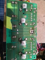
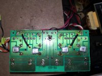
Noted! I'm finished with the power supply board, cutting where indicated... I opted to use a Dremel and go through the whole board instead of just the copper track.Nope, because then the return currents for those caps would now be polluting the return path for the speaker wire. Your binding post negative wires should go where the originals connected. Just scrape away some of the solder mask in the spot by the arrow.
Bridge wires installed aled as indicated. Decided to move bypass caps under main caps and replaced bleed resistors with a more robust option but left them in their original location.
L and R boards all done also so now it's time for cables which brings me to the first question. Since I'm replacing RCA input connectors I will relocate them to the center of the chasis. For these input cables I'm planning to use a shielded two conductor wire. Obviously each conductor goes from the RCA +&- to one of the boards (1&E1)respectively . The mesh wire shield on the RCA side will be connected also to the negative and at the board end this mesh shield will not be connected at all, only the conductors. Is that the best way? Hope that crude explanation make sense LOL
Attachments
Last edited:
Cool, power supply board looks good!
Connect the RCA shields to the negative terminal on the amp boards. Their grounds will be properly routed, as long as you connect point E2 on the amp board, back to star ground at those large-ish holes on the supply board. You want the amp's signal ground reference to match the RCA shields.
Connect the RCA shields to the negative terminal on the amp boards. Their grounds will be properly routed, as long as you connect point E2 on the amp board, back to star ground at those large-ish holes on the supply board. You want the amp's signal ground reference to match the RCA shields.
Cool, power supply board looks good!
Connect the RCA shields to the negative terminal on the amp boards. Their grounds will be properly routed, as long as you connect point E2 on the amp board, back to star ground at those large-ish holes on the supply board. You want the amp's signal ground reference to match the RCA shields.
Chris, first of all I want to thank you very much for sharing your knowledge, that was invaluable information. I completed the amp with the mods. First tested the Power Supply. TBH I was scared to hear caps popping, sparks flying and smoke raising but no, first power up after surgery without issues
 . Measured B+ B- voltages and looked OK at both boards. Then I installed the fuses on the R board and did an initial BIAS adjustment. Then the same on L board. Let the thing marinate and continued to adjust it when it stabilized more or less.
Listen Session and Initial Impressions:
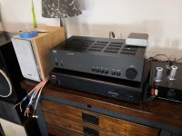
Where to start....the thing is quiet, minimum background noise (hum) you have to put your ear in the speaker to listen to it. Tried my usual flavors (rock & Jazz) using my current and loved NAD3120 as preamp.
Well the ADCOM doesnt make me as happy as my NAD. There is a lack of bottom end, mids are not well defined and the top end is decent, overall the Adcom in my opinion is not on par with the NAD3120, maybe Adcom takes the lead only in channel separation but that is it. I will give it more burn-in time but I dont think it will live to my expectations. I have heard much praise about the NAD but being my first "serious" amp it is the first time I get to compare it.
Next steps in the ADCOM as per previous comments is to match those transistors. I will need to source or DIY the means to do so at some point or buy matched pairs. Also I did not changed the 331J caps since I did not have any decent cap of that exact value to do so, not sure if that cap will make a hell of a difference to improve much the SQ.
On the other hand my father has offered his F5 Pass project, eager to star with that one soon.
Saludos!
Rob.
Attachments
Last edited:
Nice!
The matched transistors make a fairly substantial improvement to the sound, though I don't think it would affect the bass much. I'm surprised you don't find the bass satisfying; most people find that it's excellent despite it's small size. I suppose it depends on the speakers too.
The matched transistors make a fairly substantial improvement to the sound, though I don't think it would affect the bass much. I'm surprised you don't find the bass satisfying; most people find that it's excellent despite it's small size. I suppose it depends on the speakers too.
Will continue to listen and appreciate evaluating furtherNice!
The matched transistors make a fairly substantial improvement to the sound, though I don't think it would affect the bass much. I'm surprised you don't find the bass satisfying; most people find that it's excellent despite it's small size. I suppose it depends on the speakers too.
")
By the way, what is your methodology for Bias adjustment in this thing. The service manual is a bit... Shy in my opinion. How do you warm it up, what do you do with the input and output during warm up and during adjustment? Etc.
Cheers!
- Status
- This old topic is closed. If you want to reopen this topic, contact a moderator using the "Report Post" button.
- Home
- Amplifiers
- Solid State
- Yet another Adcom GFA-535