This thread is for the technical discussion of Keantoken's lateral FET 300w Class AB amp inspired by the amp in this thread. Aurum is Latin for gold and X refers to the 10 years where this amp design has languished silently, waiting to be resurrected from the ashes like the phoenix it deserves to be. The goal to develop what was touted by certain forum members to be "the best amp they have ever heard" into something more modern, using readily available components, and using state of the art layouts. Keantoken, JPS64 and myself will work to develop this into a relatively easy to build amp that can be used for projects requiring a little more oomph than usual. I currently don't have a 300w amp on hand so I thought why not go with one? I got Keantoken and JPS64 together, and away we go!
Here are the relevent design specs/requirements:
Power: 300Wpc into 8ohm (minimum Rser>5.5ohm). For 4ohm loads will require more design work, TBD.
Gain: 31.3x or 29.9db
Sensitivity 4.426Vpp or 1.56Vrms
BW: DC to ~2MHz at -3db.
Slew rate: 135V/uS
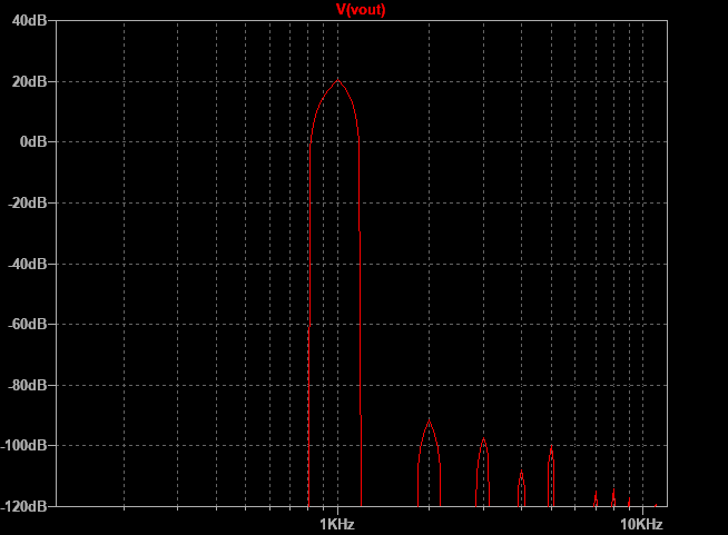
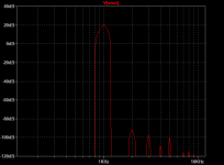
THD at 1k simulation: 0.0013% at 1KHz full power, 0.0002% at 15W. note that layout and other factors can easily add 0.0005%
We will need +/-70v rails and secondary set of rails at +/-80v for the input stage. The way to do this is still under development but an option being looked at is a custom flyback transformer/regulator.
We will be using Exicon ECX10N20 and ECX10P20 MOSFETs and they will require either Keratherm or ceramic insulator pads with thermal paste for maximum heat transfer. We need 0.1 deg C/W heatsinks to run full power.
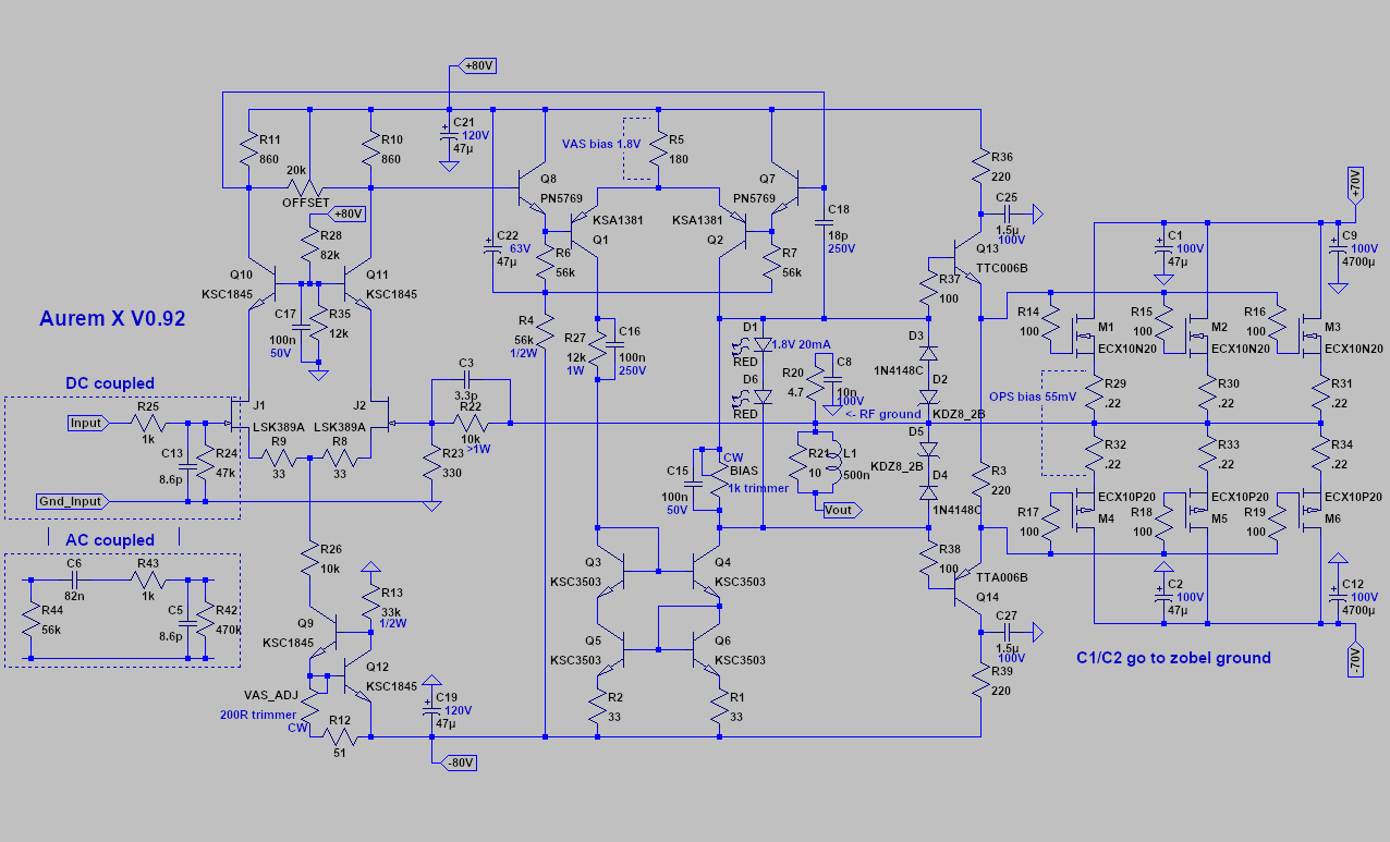
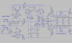
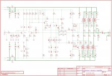
Here is the current schematic:
Predicted FFT for 15w into 8ohms:
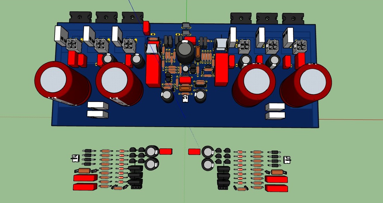
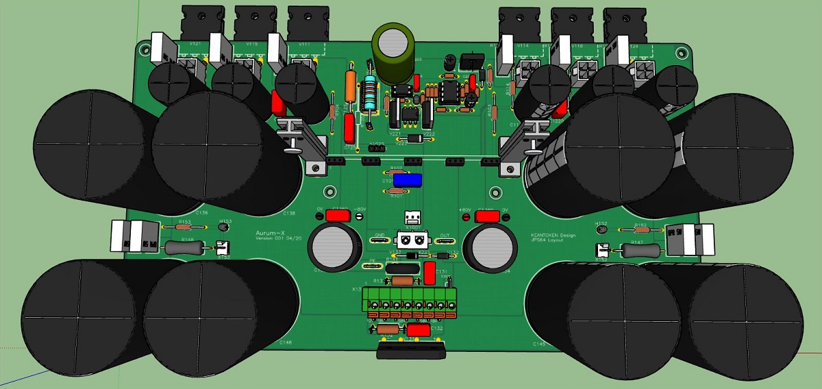
Draft placement of components so far (note optional Molex Minifit quick connects for flying leads for the outputs):
I want to thank Keantoken and JPS64 for their contributions to realize this amp. You guys are fantastic to work with! Hopefully we are not too far from a working proto.
Edit Apr. 28, 2020 - Prototype Ready Manufacturing Schematics and Renders here:
Keantoken's Aurum-X 300w Amp with LatFETs
LTspice schematic for Rev 1.0:

Render of Front End board:
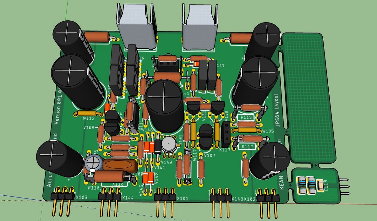
Render of Main Board (note that there is a built in solid state relay (SSR) for speaker DC protection):
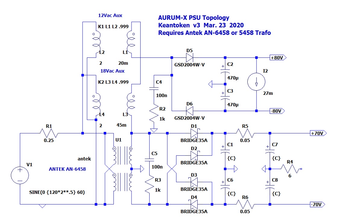
PSU Topology:
Here are the relevent design specs/requirements:
Power: 300Wpc into 8ohm (minimum Rser>5.5ohm). For 4ohm loads will require more design work, TBD.
Gain: 31.3x or 29.9db
Sensitivity 4.426Vpp or 1.56Vrms
BW: DC to ~2MHz at -3db.
Slew rate: 135V/uS
THD at 1k simulation: 0.0013% at 1KHz full power, 0.0002% at 15W. note that layout and other factors can easily add 0.0005%
We will need +/-70v rails and secondary set of rails at +/-80v for the input stage. The way to do this is still under development but an option being looked at is a custom flyback transformer/regulator.
We will be using Exicon ECX10N20 and ECX10P20 MOSFETs and they will require either Keratherm or ceramic insulator pads with thermal paste for maximum heat transfer. We need 0.1 deg C/W heatsinks to run full power.
Here is the current schematic:
Predicted FFT for 15w into 8ohms:
Draft placement of components so far (note optional Molex Minifit quick connects for flying leads for the outputs):
I want to thank Keantoken and JPS64 for their contributions to realize this amp. You guys are fantastic to work with! Hopefully we are not too far from a working proto.
Edit Apr. 28, 2020 - Prototype Ready Manufacturing Schematics and Renders here:
Keantoken's Aurum-X 300w Amp with LatFETs
LTspice schematic for Rev 1.0:
Render of Front End board:
Render of Main Board (note that there is a built in solid state relay (SSR) for speaker DC protection):
PSU Topology:
Attachments

Last edited:
Ok, let'discuss.
Sch attached.
1. Non tracking cascode will sacrifice common mode error in noninverting connection. It could be easily changed to tracking while R28 changed to some kind CCS and R35 changed to zener at LTP CCS input. Also, use low-Early effect upper BJTs, say KSC3503. It could be much better to seitch toninverting input. First you eliminate common mode at the input, next you can use sophisticated OLG tuning methods.
2. A way too low LTP load resistance. Here you lost at least 30dB of the possible gain of that kind input stage. Having such low load resistance eliminates the need of next follower.
3. Divide R13 to a pair and add soft-start cap. It's very easy, but allows the most sensitive input stage to start slowly enough.
4. Too low second LTP source resistance will anyway add distortion. It's best to place some kind of low-drop CCS here.
5. Zobel and output inductors are better to draw much righter, near to the amp output.
6. Can't find TTA/TTC006. But well-known TTA/TTC004 can't resist so much VAS current draw at +-80 rails. They have very small SOA compared even with KSC2690A/KSA1220A.
It looks wrong, but it works...
Not only does it look wrong, it's wrong. The circuit have no effect, and specially no effect against spikes and overvoltage...so the amp works.

But that doesn't matter, because the mosfets have integrated protective diodes.
Why stay at just improve while you could be one of the best?Those are interesting suggestions, but the intent of this amplifier was not to be the "best". It was to be an improvement on the original without becoming an entirely new amp.
How can you be sure it will be "best"?
I see no mention of gate diodes in the datasheet. Why don't you simulate it and get back to me?
Not only does it look wrong, it's wrong. The circuit have no effect, and specially no effect against spikes and overvoltage...so the amp works.
But that doesn't matter, because the mosfets have integrated protective diodes.
I see no mention of gate diodes in the datasheet. Why don't you simulate it and get back to me?
I sent an email to profusion/exicon asking about the gate protection diodes, they wrote back to me, today in fact, that all the lateral mosfets that they currently sell/produce, have gate protection diodes in them. The ones that did not have the diodes "-Z" are out of production, there was very little interest in those parts and the slight savings was not worth it to them to continue.
I like this circuit arrangement (or topology).
I ask kindly to you to define objectives (quality) and add SIM files and square wave behavious to 8 Ohms and also 4 Ohms.
Just remember Goldmund do not have very low simulated distortion profiles but is said as being a good sounding power amplifier. This topology is also used in ML 33 reference amplifier with a very complex circuit using only BJT (this was the best amplifier I ever heard with Wilson Audio Speakers).
Only following by now.
Regards
Ronaldo
Well that is fine too. After all the reason they are in a weird arrangement is to minimize the impact they have. I agree, Exicon doesn't give limit specs or even hint that the diodes are there so they probably want us to use our own protection.
Thank you, this is what I was going for. Lots of people like the Goldmund so it is a mistake and possibly vain to write off the design just because it doesn't seem technical or novel enough.
I like this circuit arrangement (or topology).
I ask kindly to you to define objectives (quality) and add SIM files and square wave behavious to 8 Ohms and also 4 Ohms.
Just remember Goldmund do not have very low simulated distortion profiles but is said as being a good sounding power amplifier. This topology is also used in ML 33 reference amplifier with a very complex circuit using only BJT (this was the best amplifier I ever heard with Wilson Audio Speakers).
Only following by now.
Regards
Ronaldo
Thank you, this is what I was going for. Lots of people like the Goldmund so it is a mistake and possibly vain to write off the design just because it doesn't seem technical or novel enough.
Guys,
The Goldmund is not the best amp there, but one of the good ones that audiophiles could well copy. And its a classic, worth recreating here. Kean wants to replicate the original, a worthy goal, and he wants to build it with X and offer it free of change to the members.
Why not let them do it without criticisms? If YOU have problems with that, go through the steps he is retracing and do a better one, then put it up for others to critique. It is not comfortable publishing your complete work, try it yourself and see how it feels.
I will never understand why people try to hijack good ideas of perfectly very good commercial amps. If you discourage Kean and he pulls the plug on this project, we will all be the more poor.
HD
AKSA,
I have to wonder who you are directing this at,
I have to wonder who you are directing this at,
Have to be careful with who you direct these statements towards, using a broad brush, can scare everyone away. Do you think I am criticizing?, thought I was trying to help member Kentoken. If you think I am, I can go away, not like I do not have projects of my own designs to work on, just taking a break from soldering up boards in fact.Why not let them do it without criticisms?
- Home
- Amplifiers
- Solid State
- Keantoken's Aurum-X 300w Amp with LatFETs