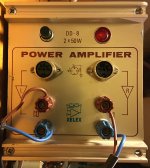
Does anyone know anything about this amp? I bought it recently on a Swedish auction site, and my original thinking was that if it was not functional, then I could repurpose the case for a tube amp.
It was missing the cap on the fuse holder, so I replaced the holder and fired it up with a variac, and I had sound from one channel. I do not have the right input plugs so I had used wires into the holes, so maybe I had not made a good connection. I will check again.
The channel that was working was OK - not spectacular, but difficult to judge when it is just one half the stereo signal.
It would be good to know if I should be treating this as an object that ought to be repaired and passed on to someone who would value it, or treated as a run-of-the-mill PA amp from the 70's, that is fair game to be re-purposed.
Attachments
If I were swedish, I would be really proud to listen daily to something made in Sweden. Particularly in a world where consumer electronics can be expected to last at least 10 months past the warrenty expiration. (my 2017 samsung 32" TV lasted almost 23 months before it wouldn't turn on). The lords of commerce want us to send everything to the landfill in 2 years and buy new. This amp could be repaired by an ordinary guy with a $50 soldering iron, $25 analog & DV meters, $20 in tools.
Those TO5 drivers are rare and can be very nice if they are the RCA 2n2102 clones with high Ft. I have one surviving pair of RCA 40409/40410 that really sound good as drivers with modern 3 mhz output transistors. 1970's output transistors with 400 khz Ft can cause distorted highs. I had to buy $3 MJE15028/29 drivers to equal the sound of the 40409/40410. (down to $1.20 now). TIP31c/32c with 3 mhz Ft distorted the highs like top octave solo piano or tinkly percussion.
As most distortion is in the speaker, I listen 12 hours a day to boards with .1% to .06% HD (harmonic distortion). 3rd & 4th digit HD is for bragging, not listening IMHO. I had to modify my ST120 to get adequate output transistor idle current when it was cold. 20 ma on emitter resistors is fine on TO3 transistors.
50 watts/channel is entirely sufficient for a house setting. I listen at 1/8 watt base level with 101 db 1W1m speakers. I can get 70 W peaks of 5 seconds out of my ST120. Had to wear earplugs to test that. I bet you can get more than 50 W with more fins on the heat sink or a fan. Depends on the rail voltage. ST120 is 70 v, so high because in 1972 output transistors had gains of 5. Peak voltage can be 1/2 of rail voltage, if the transistors don't melt. I tack TO3 finned heat sinks naked to aluminum sheet heat sinks to add fins, with a little heat sink compound to make it flow. Drill holes & use 3 mm screws and elastic stop nuts (4-40 in the US).
So happy listening, or sell it off to a diy fan of classic aluminum/silicon/film.
Last edited:
Hi indianjo, and thanks for the comments!
My thinking when I bought it was that if it was unserviceable, then the case would make an ideal home for a small valve PP amplifier, something like 4 PCL86's to keep the part count down, with a couple of power transformers as OPTs, and a voltage quadrupler PS. I'm aiming for 12W + 12W max, so have no concerns about power output.
My limited expertise is with valve amplifiers, and I think I am capable to identify the stages in a valve amp, and pinpoint an issue in a particular stage. Solid state is another ball game, and I am also hampered because I cannot find the schema for this amplifier.
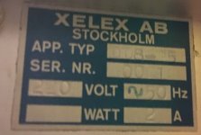
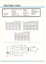
The construction of the amplifier is top notch. Supposedly it was used by Sverige Radio, and the form factor is very similar to a Quad II, which they were big users of.
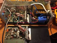
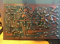
There are 4 screws on each end plate, and the whole thing folds out. The PCBs just slide out of grooves, so accessibility is perfect, even though it is compact when screwed back together.
One channel is dead, and there is nothing obvious scorched to help identify the issue. I had also thought that if it was working OK, I would use it with a tube preamp, so I'd get the sound I love, with the convenience of input selectors and volume of the pre-amp. I am easily pleased! ;-)
If I can locate a schematic then I'll see what I can do. When I bought it the fuse was missing, and the smoothing capacitors had been replaced, so I suppose that someone has also tried to solve some issues.
Thanks again!
Richard
My thinking when I bought it was that if it was unserviceable, then the case would make an ideal home for a small valve PP amplifier, something like 4 PCL86's to keep the part count down, with a couple of power transformers as OPTs, and a voltage quadrupler PS. I'm aiming for 12W + 12W max, so have no concerns about power output.
My limited expertise is with valve amplifiers, and I think I am capable to identify the stages in a valve amp, and pinpoint an issue in a particular stage. Solid state is another ball game, and I am also hampered because I cannot find the schema for this amplifier.
The construction of the amplifier is top notch. Supposedly it was used by Sverige Radio, and the form factor is very similar to a Quad II, which they were big users of.
There are 4 screws on each end plate, and the whole thing folds out. The PCBs just slide out of grooves, so accessibility is perfect, even though it is compact when screwed back together.
One channel is dead, and there is nothing obvious scorched to help identify the issue. I had also thought that if it was working OK, I would use it with a tube preamp, so I'd get the sound I love, with the convenience of input selectors and volume of the pre-amp. I am easily pleased! ;-)
If I can locate a schematic then I'll see what I can do. When I bought it the fuse was missing, and the smoothing capacitors had been replaced, so I suppose that someone has also tried to solve some issues.
Thanks again!
Richard
Last edited:
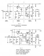
I see only 6 transistors, 1 TO92, 3 TO5, two TO3. Depending on whether the output transistors are npn+pnp or npn+npn, I'd take a standard schematic diagram and try to trace the differences. Here for example is the 1967 Haas Motorola 60W complimentary amp presented at AES.
By contrast the 60 W amp by bilbo has only a single input transistor, which looks like maybe what you have.
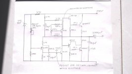
Main limiter to distortion on these very old amps are the slow output transistors. Four $3 MJ15015 quasi comp or pair MJ15015 and MJ15016 could pep the sound right up. Don't forget the 10 ohm base drive resistors shown on bilbo, they are required on modern fast output transistors to prevent oscillation, especially as the output transistors are remote from the board. I flew 1 W 10 ohm resistors in the air on the ST120, instead of the wires from the PCB.
I fix such things with a DVM, analog VOM & FM radio, so it doesn't take a huge expensive committment to getting these appliances running again.
By contrast the 60 W amp by bilbo has only a single input transistor, which looks like maybe what you have.
Main limiter to distortion on these very old amps are the slow output transistors. Four $3 MJ15015 quasi comp or pair MJ15015 and MJ15016 could pep the sound right up. Don't forget the 10 ohm base drive resistors shown on bilbo, they are required on modern fast output transistors to prevent oscillation, especially as the output transistors are remote from the board. I flew 1 W 10 ohm resistors in the air on the ST120, instead of the wires from the PCB.
I fix such things with a DVM, analog VOM & FM radio, so it doesn't take a huge expensive committment to getting these appliances running again.
Attachments
Last edited:
This one reminds me of some ampmodules I had.
3 of them were supposed to be slided in to a 19" rack chassie, they had slide pots on the front.
In the back there were some kind of fast connector that connected when it was slided in.
PCB's looked the same. Metal can transistors, 40409 and 40410 as drivers IIRC. 2 pairs of 2N3772 on output.
There were also output transformers, really heavy ones.
The parts are here somewhere...
Also made in Sweden.
BR
Figge
Was long time ago but if memory serves...
They often used BDY56 in a quasicomplementary output with a Baxandall diod.
Later models DD10 used a diff-stage input and a complementary VAS, perhaps DD8 is similar.
The model used by SR was D7, a mono model.
I might have a few BDY56 if they has blown.
/örjan
They often used BDY56 in a quasicomplementary output with a Baxandall diod.
Later models DD10 used a diff-stage input and a complementary VAS, perhaps DD8 is similar.
The model used by SR was D7, a mono model.
I might have a few BDY56 if they has blown.
/örjan
Thanks all for the useful pointers.
I noticed that if I disconnected the inputs on the good channel, it is always quiet. But disconnecting the ground on the bad channel results in a sort of high pitched and distorted motor boating. Is that a smoking gun behind the grassy knoll?
I noticed that if I disconnected the inputs on the good channel, it is always quiet. But disconnecting the ground on the bad channel results in a sort of high pitched and distorted motor boating. Is that a smoking gun behind the grassy knoll?
I use a 3 mm stereo phone plug to dual RCA plug adapter cable. As you don't have RCA jacks, I'd first install some, or 1/4 phone jacks or a stereo jack of either size. Buy appropriate adapter cable. That connector on the back you have is for rack mounting, won't be reliable while you are testing with just a pin stuck in the hole. Use safety glasses when drilling with power tools. If you find a matching connector (looks like DIN) great!
Set the radio to about 1.6 vac output (about 1/5 volume, radios will go to 7 vac on the earphone jack).
Don't use a $600 cell phone instead of a $10 radio, if DUT (device under test) puts DC out the input jack it will blow up your phone. Buy an old walkman or something at the pawn shop. I found my test radio in the trash at work. Battery clips corroded and volume pots worn out kill cheap radios, both are easily repairable. Bypassed the volume pot with a fixed resistor since I couldn't find an exact match.
Using 2 or 20 vac scale of ANALOG vom, or scope or sound probe, look at collector of input transistor. If tuned to a rock station, you should see the drum beats of the music on the pointer. AC scales, you need a .047 uf >200 v capacitor in the negative lead of the meter to prevent response on DC signals.
Note DVM average over 2-4 seconds so will show oscillation the same as music. Also the cheap ones make random numbers on frequencies other than 50-60 hz. The expensive DVM (fluke RMS model) ignores frequencies over 7 khz so will totally miss ultrasonic oscillation. Waste of money to buy one of those. Analog VOM caught 1 mhz oscillation on my op amp swap project.
If no AC (music) at input transistor collector, back up and look between input cap and resistor to base of transistor. Should be AC voltage there. AC Voltages are not visible on bases, those respond to current.
I saw a analog VOM with 20 vac scale for $30 at the discount store last week in the auto accessory department. Doesn't require a huge committment to buy one. I use a Simpson 266XLPM that I bought for $280 in 1986 and it has no electrolytic caps to expire on the shelf, unlike used scopes that are full of them. Just activated the B&K 2120 scope I bought in 2002, took 12 e-caps just to make the horizontal sweep move. Took 4 hours to get the glue off to remove the pcb to turn upside down. 80 ecaps more to go to a reliable test device. Scope un-substituteable for tracing 50 db down hum, which is the problem I have on my AX6 today. Analog VOM is fine for tracing no sound problems.
Be aware when checking with power on, use only one hand at a time. Voltage over 24 across your heart can stop it. Put meter negative on speaker ground with an alligator clip lead. Wear no jewelry on fingers, hands, or neck. 1 v at 50 A can burn your flesh to charcoal through a ring. Don't work alone, don't work distracted by gadgets or conversation. When turn power off, don't touch metal until measured under 1v, then discharge rail caps with resistor as necessary.
Have fun. Fixing amps is more rewarding than crossword puzzles.
Last edited:
- Status
- This old topic is closed. If you want to reopen this topic, contact a moderator using the "Report Post" button.
- Home
- Amplifiers
- Solid State
- Xelex DD-8