During my forays into the Class A world I read an article that stated that this design is very good.
It originally appeared in Electronics World in September 1996 and subsequently appeared in Rod Elliots pages.
My question is will it actually work ? TR4 appears to have no base biasing ?
It originally appeared in Electronics World in September 1996 and subsequently appeared in Rod Elliots pages.
My question is will it actually work ? TR4 appears to have no base biasing ?
Attachments
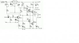
This was a JLH variation as I recall. TR4 is biased to the 0 volt line which is correct... just like an opamp input. Remember it is a split supply, not single rail.
The original diagram had an error as I recall which looks corrected in this version. Feedback cap connected to the neg rail? in the incorrect version.
The original diagram had an error as I recall which looks corrected in this version. Feedback cap connected to the neg rail? in the incorrect version.
This was a JLH variation as I recall. TR4 is biased to the 0 volt line which is correct... just like an opamp input. Remember it is a split supply, not single rail.
The original diagram had an error as I recall which looks corrected in this version. Feedback cap connected to the neg rail? in the incorrect version.
Yes, I corrected the original schematic in Paint before posting it.
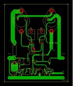
I knocked up a few PCBs
This is my layout.
Yes, I forgot the 100uF supply decouplers, they are soldered onto the bottom of the board.
It is only a single layer board, the top layer trace was a mistake and is just a wire link.
It doesn't seem to matter how often you proof read a project, there will always be mistakes in the final draft.
Attachments
Do yourself a favour and also look at The Class-A Amplifier Site (TCAAS) hosted by Rod Elliot. There is an alternative to this one where four output BJTs are used to spread the heat load. It is a Geoff Moss design. The PCBs are/were available on Ebay. Will see if I can find the link.
Kevin
P.S. I would also suggest that you do a dual mono block design - 2 off 200VA trafos with a CRC-CapMx PSU. Also look at the The Alpha Big Boy with Buttah (ABBB) 52w Class A Amp GB thread.
Kevin
P.S. I would also suggest that you do a dual mono block design - 2 off 200VA trafos with a CRC-CapMx PSU. Also look at the The Alpha Big Boy with Buttah (ABBB) 52w Class A Amp GB thread.
Last edited:
TR4 is biased, its emitter is tied to -22v through R5. Its base is at around zero.
You must have ment the collector tied to R5 here.
The base is near 0V through R3 and R2; Tr4 base current is flowing out through R3+R2, say approx 5µA range, so, at +(0.1 <> 0.2)V, The emitter of Tr4 is adjusted with RV1 to a current of approx 0.5mA, so it is at +(0.5 <> 0.7)V.
A fraction from RV1+R1 will flow through R8 towards the output near at 0V.
The Tr5-Tr combo acts as a passive current source.
You must have ment the collector tied to R5 here.
Indeed [emoji13]
Neither of the articles that I have read have explained what the two pot's do and how to set them ?
Has anyone any ideas ?
I'm guessing that RV1 is adjusted to give approx. 11V across R1.
I'm guessing that RV2 is adjusted to give approx. 0.33V across R10.
Class A at 25W with +/-22V rails. I'm guessing that Iq is going to be about 1A.
Has anyone any ideas ?
I'm guessing that RV1 is adjusted to give approx. 11V across R1.
I'm guessing that RV2 is adjusted to give approx. 0.33V across R10.
Class A at 25W with +/-22V rails. I'm guessing that Iq is going to be about 1A.
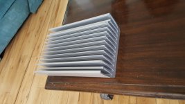
To get 25W of output power with an 8 Ohm load, output voltage will be +/- 20Vpp and current will be +/- 2.5 App. To stay in Class A, Iq must be 2.5A DC (the circuit is SE)! This biasing will translate into 62.5 W dissipation (with +/- 25 V rails) per output transistor. In total, the heatsink must be able to dissipate 125W - this is massive and Rth should be << 0.5 K/W to limit transistor case temp to a reasonable level.
- Status
- This old topic is closed. If you want to reopen this topic, contact a moderator using the "Report Post" button.
- Home
- Amplifiers
- Solid State
- 25W Class A Amplifier