[UPDATED: Workbook here - Google sheets workbook with all the information organized.]
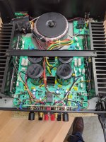
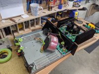
I've done a bunch of google searches and not found too much on this particular amplifier, insofar as repair and upgrade. The power caps have leaked, and one of the power fuses is blown. I have the whole amp apart which is in otherwise beautiful condition. I'd like to replace where prudent (while I'm here) and upgrade where that's sensible.
Filippo
I've done a bunch of google searches and not found too much on this particular amplifier, insofar as repair and upgrade. The power caps have leaked, and one of the power fuses is blown. I have the whole amp apart which is in otherwise beautiful condition. I'd like to replace where prudent (while I'm here) and upgrade where that's sensible.
- 15000 uF Nichicon caps are here now, and all leaking. Suggestions here?
- I'm wondering about the electrolytic caps that are here, while everything is open. Replace? Suggestions?
- Any resistors I should be considering for upgrade?
Filippo
Last edited:
Replace the 15000uF caps with the same value and at least the same voltage rating, high ripple current is also desirable for power supply filter capacitors. Capacitors with a 105 degrees celsius temperature rating will increase lifespan.
Nichicon , Panasonic, Rubycon, Nippon Chemicon, Cornell Dubilier
are reputable manufacturers of capacitors try searching their websites for suitable replacements, check physical measurements to make sure that the new capacitors will fit.
You may as well replace the other electrolytic caps while its open, you can use any from the above manufacturers, don't waste your money on silly audiophile components.
You don't need to replace any resistors unless they appear to be burnt or measure different to their original values. Replacing resistors won't improve improve audio quality.
For the big caps, Nichicon LKG1K153MKZ seem like the ticket, available easily in the USA. They are 80V, another 20mm taller, which easily fits below the cover, but will require moving the heat sink cross brace which is simply done by drilling and tapping two new screw holes in the heat sinks.
I'll run through and assemble a cap inventory tomorrow. Thanks for the feedback.
Filippo
I'll run through and assemble a cap inventory tomorrow. Thanks for the feedback.
Filippo
Since I'm in Google Docs, easy enough to share out info I'm collecting as I go through the process of working over this amplifier. Hope this is helpful to someone. From this workbook, one has links and access to everything.
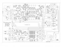
Workbook: Parasound HCA-1500a - Google Sheets
Filippo
Workbook: Parasound HCA-1500a - Google Sheets
Filippo
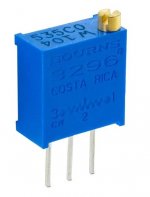
Thank you, Patrick. The VR is marked T205 ... which I suspect at 2MΩ trim pot. Oddly the schematic is marked 2K? Not sure on wattage, either.Big caps Nichicon LKG1K153MKZ is good, replace all the e-caps, replace BIAS VR with multi turns VR, all new fuses, mod the driver current and reset BIAS. It will be OK.
I know this is rather benign, do you have a specific recommendation for the multi-turn?
Filippo
Mods
I just recently got one from a pawn shop, $100. Still in operational condition and haven't connected it to anything. Yet like you I have plans to "upgrade" it. I have also collected the mod suggestions by John C for the 3500, marked the schematic for that amp and now in the process of equating those mods to this design where appropriate. At least to my thinking. It is suggested because of the age and likely environment these operated in, cap replacement is recommended. R112 is equivalent to the feedback resistor John said to replace in the 3500 with a Holco(old type), and check the polarity of the AC input was suggested. I personally will remove the attenuator input pots(yuk). One additional physical issue I have with the design. The builders used rather small dual run jumper through many junctions to power the output of this " high current output" anp. I plan on augmenting the flow of current through this circuit..
Also, it was suggested to remove some of the film bypass caps on the main buss caps. Never in the original design. Someone out there I read found that those main caps were just fine. Might scope the ripple before spending the money to replace.
Have to listen to it first however....
Last edited:
The VR is marked T205 ... which I suspect at 2MΩ trim pot. Oddly the schematic is marked 2K? Not sure on wattage, either.
Filippo
The VR is for the BIAS control and the value can't be large, so that 2K is for sure and low wattage is OK. We usually use something like Bourns 3296 Trimpot, it should be 1/2W.
Attachments
One additional physical issue I have with the design. The builders used rather small dual run jumper through many junctions to power the output of this " high current output" anp. I plan on augmenting the flow of current through this circuit..
You can use copper to make some of the power supply bar to replace the jumper wires.
Attachments
Thank you, Patrick, Bourne 3296Y-1-205 looks good: Mouser pageThe VR is for the BIAS control and the value can't be large, so that 2K is for sure and low wattage is OK. We usually use something like Bourns 3296 Trimpot, it should be 1/2W.
Filippo
Nice. I started at $150, the chassis is as new so I was pleased. Non-working but blown fuse and I knew I was going through it. I don't have the benefit of listening first, it's apart for repair, and just going to have it open onceI just recently got one from a pawn shop, $100. Still in operational condition and haven't connected it to anything. Yet like you I have plans to "upgrade" it.
") .
.We must be on parallel paths! I'm waiting for an HCA-3500. Want to mate it to my Klipsch Epic CF-4's. I live out in a rural area and ... some guy posted one on Craiglist 20 miles from me ... for $900 and I didn't jump fast enough. Patience. In the meantime, I'm working this amp.I have also collected the mod suggestions by John C for the 3500, marked the schematic for that amp and now in the process of equating those mods to this design where appropriate. At least to my thinking.
I have done reading on the HCA-3500, seen John Curl's posts. If you share your collection of info, it would be nice to see. I decided to document work on this mostly because I spent hours chasing bread crumbs and hope this thread and info will help others and make it worthwhile for some folks to chime in.
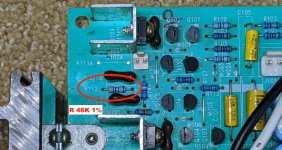
Thank you. I've added this to my list. The R112 is pesky to find. I've attached a photo to find it. It's a 46k 1% tol resistor. BTW in the post I read, John said old Holco or Resista.It is suggested because of the age and likely environment these operated in, cap replacement is recommended. R112 is equivalent to the feedback resistor John said to replace in the 3500 with a Holco(old type) ...
Any pointers on where to find NOS Holco resistors? A quick search tells me new stuff and unclear old stuff. In the post I read, John says old Holco or Resista, btw.
Oh?... and check the polarity of the AC input was suggested.
Copper bars Patrick showed are nice, but looks like a PITA. Dig in and let us know how that goesI personally will remove the attenuator input pots(yuk). One additional physical issue I have with the design. The builders used rather small dual run jumper through many junctions to power the output of this " high current output" anp. I plan on augmenting the flow of current through this circuit..
I saw that on the HCA-3500. I'm going to leave this one alone as I figure eventually this amp will be replaced by the 3500 when I find it.Also, it was suggested to remove some of the film bypass caps on the main buss caps. Never in the original design. Someone out there I read found that those main caps were just fine. Might scope the ripple before spending the money to replace.
One benefit you have that I didn't! Thanks for posting and please don't hesitate to chime in.Have to listen to it first however....
Filippo
Attachments
Last edited:
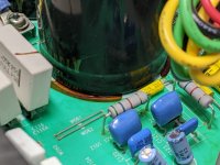
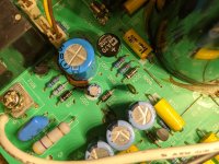
So one thing to note, along with leakage on the big power filter caps, one other cap that leaked was a C021 which is a 1000uf 25V electrolytic cap. This guy may qualify for upgrading...
Filippo
After remove the cap, better clean the brown glue on the PCB. Some glue may conduct circuit and cause problem.
Thank you, yes I was planning on cleaning the board once everything comes off.After remove the cap, better clean the brown glue on the PCB. Some glue may conduct circuit and cause problem.
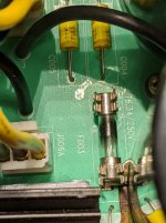
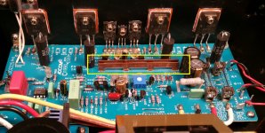
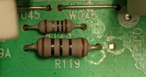
So in this thread, you note replacing R119 and R120 with a 47k 2W resistors. You mention those two resistors are originally 100k, but mine are 200k by my calculation. Am I missing something?
Filippo
Attachments
Last edited:
So in this thread, you note replacing R119 and R120 with a 47k 2W resistors. You mention those two resistors are originally 100k, but mine are 200k by my calculation. Am I missing something?
Filippo
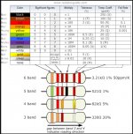
In your photo, R119 is 100R, the upper one is 10R which is one the power output transistors base resistor. You can follow below resistor color code calculate the resistance. First three color is the value and times the forth color, so that R119 is 100R. You also find out the R120 of the same color code and size, remove them and add a 47R 2W between the mosfet driver legs.
I'm sorry, forget to mention before replace the BIAS VR, we should first measure the old VR resistance. After replace new VR, we first tune VR to the old value before new BIAS set.
Attachments
Last edited:
I saw the diagram, but read the first color wrong, at the end of the day of staring too long at too many things . Thanks.
R112 seems to want to get a 47k 1/2W 1% non-magnetic resistor. Having a heck of a time finding a source for that. I've seen old Holco stock or Resista suggested, but I've yet to find a source.
R119 and R120 - anything special about which 47k 2W resistor they get? Or any one will do?
Thanks again! Almost ready to order all the parts ...
Filippo
. Thanks.R112 seems to want to get a 47k 1/2W 1% non-magnetic resistor. Having a heck of a time finding a source for that. I've seen old Holco stock or Resista suggested, but I've yet to find a source.
R119 and R120 - anything special about which 47k 2W resistor they get? Or any one will do?
Thanks again! Almost ready to order all the parts ...
Filippo
- Home
- Amplifiers
- Solid State
- Parasound HCA-1500A repair and possible upgrades