OK, that explains that then.
You turn the bias preset to give minimum (the lowest) resistance as measured between the collectors of Q7 and Q8. We do this for initial powering up.
With RV1 on minimum you have the equivalent of a 56 ohm in parallel with a 270 ohm so you should read around 47 ohms in theory.
And double and triple check those transistors are fitted correctly, there are no second chances when you power it up")
You turn the bias preset to give minimum (the lowest) resistance as measured between the collectors of Q7 and Q8. We do this for initial powering up.
With RV1 on minimum you have the equivalent of a 56 ohm in parallel with a 270 ohm so you should read around 47 ohms in theory.
And double and triple check those transistors are fitted correctly, there are no second chances when you power it up
Attachments
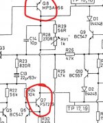
Minimum could be clockwise or anticlockwise, it all depends how the pins are configured on the PCB. Measure the resistance between the collectors of those transistors as I outlined before. Turned one way will be obviously lower resistance than when turned the other way. Set it for the low resistance.
There isn't much point marking the setting because the amp would (all being well) be set up from scratch with the bias adjusted correctly once its proved all OK.
Different semiconductors will change the set bias point in any case so it has to be readjusted.
Switching on with the bias at a minimum is always safer after performing any repair work.
It's working!! Sound is very clear on both channels. I will leave it on for a while with the bulb limiter to see if it is stable. Then I guess I need to adjust the bias accordingly. Would you mind also helping me with that Moody or at least point me in the right directon?
Wonderful 
Bias should be fairly easy to set, The manual suggests a current of 32 milliamps, however we set this by careful voltage measurement across the 0.22 ohm resistors.
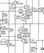
Look at the diagram. There are two test points shown per channel and these are on the 0.22 ohm resistors.
Measuring end to end across the two resistors (so the total resistance is 0.44 ohms) we aim for 14 millivolts. That is 7 millivolts across each resistor.
(I=V/R which is 0.014/0.44 which is 0.032 or 32 milliamps)
This is a very small voltage and it will alter a lot as the amp warms. It might be easier to first tag some wires to those test points and connect your meter first. You are measuring just a few millivolts here. Polarity doesn't matter.
Have no signal applied and also have the speakers disconnected.
Aim for 14 millivolts when the amp has been on a good while.
Bias should be fairly easy to set, The manual suggests a current of 32 milliamps, however we set this by careful voltage measurement across the 0.22 ohm resistors.
Look at the diagram. There are two test points shown per channel and these are on the 0.22 ohm resistors.
Measuring end to end across the two resistors (so the total resistance is 0.44 ohms) we aim for 14 millivolts. That is 7 millivolts across each resistor.
(I=V/R which is 0.014/0.44 which is 0.032 or 32 milliamps)
This is a very small voltage and it will alter a lot as the amp warms. It might be easier to first tag some wires to those test points and connect your meter first. You are measuring just a few millivolts here. Polarity doesn't matter.
Have no signal applied and also have the speakers disconnected.
Aim for 14 millivolts when the amp has been on a good while.
Attachments
If you do this first with the bulb tester in place then the bulb will start glow a little. That shows the adjustment is working correctly however the adjustment must be done without the bulb.
So once you are happy with the procedure with the bulb fitted you should turn the bias back to minimum, then remove the bulb and now set the bias for real.
So once you are happy with the procedure with the bulb fitted you should turn the bias back to minimum, then remove the bulb and now set the bias for real.
Thanks Mooly. So just to confirm I attach the multimeter probes via wires connected to TP 14 and TP 15 respectively and then, after the amp has been on a while, adjust RV101 until I have a reading of 14 millivolts?
That's it. You can also compare with the other channel for interest but don't alter that one at this point.
One thing I found in the manual is that the figure is different depending on which version of the amp you have. Measuring across both resistors gives you a higher voltage to work with which can be more accurate... nothing else changes, it is just the measurement method.
7mv across one resistor means there will be 14 millivolts across the pair.
I see you deleted that post just this instant
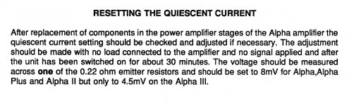
The diagrams show 7mv, the write up says 8mv and also adds this:
Attachments
Haha yes. I felt I was being a little over cautious asking for confirmation, especially considering you had explained things so clearly, so I deleted it. Thanks for quoting it for the sake of continuity!
I'm waiting for the amp to warm up as we speak. The meter is currently reading 5mv with RV1 on minimum. I will give it half an hour as stated in the thumbnail however I notice that the attachment also states 4.5mV for Alpha 3 across one of the resistors. Should I be looking at a reading of 9mV total therefore as mine is an Alpha 3?
I'm waiting for the amp to warm up as we speak. The meter is currently reading 5mv with RV1 on minimum. I will give it half an hour as stated in the thumbnail however I notice that the attachment also states 4.5mV for Alpha 3 across one of the resistors. Should I be looking at a reading of 9mV total therefore as mine is an Alpha 3?
That's how it reads... it would be 9mv across the pair, or 4.5mv across each one.
Its not super critical and anything over a millivolt or two will remove any audible distortion.
Don't be tempted to go higher thinking it will sound better... it won't.
Also the real problem and danger of going higher is excess heat (its runs hotter) and also the danger of thermal runaway where as it gets hot when playing loud the current tends to increase and so it repeats... its gets hotter and hotter and self destructs.
Err on the lower side rather than higher.
Its normal. Bias current is often very loosely controlled and very subject to temperature change of the semiconductors. Its perfectly normal.
Having proved it all seems basically OK I would definitely recommend you now turn the bias back down again on this channel and then reset it again when the bulb is removed.
This is because the bulb will be reducing the rail voltage in the amp and the bias current is probably influenced a little bit by that.
The rails will be higher without the bulb and the bias probably higher as well. The other channel may well end up higher than the 6mv you have just measured.... its worth checking for curiosity.
Thanks Mooly. I'm playing the amp as normal now i.e. without current limiter but through some test speakers just in case. It sounds fine so far - just a very slight pop when I turn the power on/off. Do you think it it is still wise to replace Q7 and Q8 on the other channel as suggested earlier? I also have replacements for Q11 and Q12 if necessary.
Btw I tested the transistors I removed and from what I can tell Q8 was faulty. With the multimeter set to diode mode I put the -ve probe on the base and touched the other legs in turn with the +ve probe. The emitter gave a reading of about 8.3 but the connector nothing.
Btw I tested the transistors I removed and from what I can tell Q8 was faulty. With the multimeter set to diode mode I put the -ve probe on the base and touched the other legs in turn with the +ve probe. The emitter gave a reading of about 8.3 but the connector nothing.
Its up to you whether you want to do the same to the other channel. If you have identical parts to those used for the repaired channel then I suppose it makes sense.
If you do then remember to use the bulb again and to turn the bias to minimum on this other channel.
In other words exactly the same procedure is taken as that we have just done.
If you do then remember to use the bulb again and to turn the bias to minimum on this other channel.
In other words exactly the same procedure is taken as that we have just done.
OK sure. Thanks Moody. I will perhaps leave it for the moment and just enjoy the amp for a while as it is. Don't want to push my luck! That said now I know the procedure I will feel much more confident tackling things next time.
Once again. Thanks for all your help with this. Truly extraordinary and deeply rewarding having achieved what I thought I would never be able to tackle. Best regards. Nick
Once again. Thanks for all your help with this. Truly extraordinary and deeply rewarding having achieved what I thought I would never be able to tackle. Best regards. Nick
- Status
- This old topic is closed. If you want to reopen this topic, contact a moderator using the "Report Post" button.
- Home
- Amplifiers
- Solid State
- Arcam Alpha 3 right channel fuse keeps blowing