Did a recap in my Nad c272 and after that everything works perfect except the turn on delay... i turns on after 1/2 second and before recap it was perhaps 3-4 seconds. In my opinion too fast.
What component is making trouble? I’ve triple check everything (especially caps around the protectioncurcuits etc)
This unit doesn’t have the 1237 pr chip, its a new replacement from nad
Anyone know what i can do to correct this?
What component is making trouble? I’ve triple check everything (especially caps around the protectioncurcuits etc)
This unit doesn’t have the 1237 pr chip, its a new replacement from nad
Anyone know what i can do to correct this?
Attachments
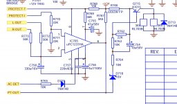
It will be the cap on pin 7 that sets the delay from power on to relay engaging.
This was 47uf jianhong cap and i replaced this with a rubycon zlj with same value.. hmm.
What i do notice is after after power off for long time (several days) it will take a bit longer (maybe a second more?) but still second time it will go very fast again.
If i put 100uf will this delay the action?
It sounds like that cap isn't discharging after turnoff, or discharging much too slowly. That could explain the symptoms. If it retains some charge then the delay won't work properly. There should be a path to ground through a high value resistor to bleed off the charge, but I'm having difficulty reading that schematic. Possibly that path goes through the "PT-OUT" connection?
It sounds like that cap isn't discharging after turnoff, or discharging much too slowly. That could explain the symptoms. If it retains some charge then the delay won't work properly. There should be a path to ground through a high value resistor to bleed off the charge, but I'm having difficulty reading that schematic. Possibly that path goes through the "PT-OUT" connection?
Ok, thx that make sense. I will check and get back.
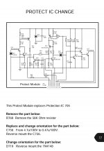
The replacement module eliminates timing resistor R769 (56K) and replaces it with an on-module resistor R24 which is now 180K. The timing resistance has increased by a factor of 3. So the circuit's ability to tolerate leakage in the timing capacitor just decreased by a factor of 3.This unit doesn’t have the 1237 pr chip, its a new replacement from nad
I think it might be a good idea to purchase an 0.47uF 50V electrolytic capacitor which is specifically designed for lowest leakage. Such as the Nichicon "KL" series. Mouser sells them: 647-UKL2AR47KDD.
And as long as you're placing an order anyway, you might as well buy several different capacitor values from the KL series. This gives you the opportunity to experiment with different capacitor values to achieve whichever turn-on delay that YOU like best. Perhaps these seven different capacitors (mouser short-link below). It's completely YOUR choice, of course!
short-link to 7 KL capacitors at Mouser.com
_
Attachments
The replacement module eliminates timing resistor R769 (56K) and replaces it with an on-module resistor R24 which is now 180K. The timing resistance has increased by a factor of 3. So the circuit's ability to tolerate leakage in the timing capacitor just decreased by a factor of 3.
I think it might be a good idea to purchase an 0.47uF 50V electrolytic capacitor which is specifically designed for lowest leakage. Such as the Nichicon "KL" series. Mouser sells them: 647-UKL2AR47KDD.
And as long as you're placing an order anyway, you might as well buy several different capacitor values from the KL series. This gives you the opportunity to experiment with different capacitor values to achieve whichever turn-on delay that YOU like best. Perhaps these seven different capacitors (mouser short-link below). It's completely YOUR choice, of course!
short-link to 7 KL capacitors at Mouser.com
_
So many thx for that. Impressive knowledge you sit on.
You don’t mean the 47uf cap? I thought that was the one. So it’s the 0,47uf that handles it?
I often order from mouser and digikey so i can order some. What’s max capacitance i could go up to? (Or try)
C756 is there to 'lightly' smooth the raw AC from the power supply, it is not a used as a timing cap as far as I can see. It is just to provide an indication of AC being present or not and presumably allows a fast drop out of the relay on detecting power off.
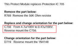
I notice they say that if the module is fitted then the diode and cap will have been reversed in polarity... however the PCB is possibly marked for using the chip.
Have you fitted C756 correctly with regard to polarity?
C755 is the timing cap and Mark does makes a valid point over leakage although I wouldn't really expect an issue with good quality parts.
I checked now and in that position i have a wima mks 0,47uf because that’s what i had at the time. Wouldn’t a electrolytic have more leakage?
Yes, the board has original marking despite ”version 5.0” and schematic shows 3.0 or 3.7
I noticed this when i replaced a zener there and the amp went to protection right away and then i remember the schematic says ”reverse D718”, and after that ofcourse it worked again.
Yes, the board has original marking despite ”version 5.0” and schematic shows 3.0 or 3.7
I noticed this when i replaced a zener there and the amp went to protection right away and then i remember the schematic says ”reverse D718”, and after that ofcourse it worked again.
Last edited:
") A 0.47uF film cap should be fine.
A 0.47uF film cap should be fine.Why not refit your original electrolytic cap back in place for C755 as a test. It has to be something you have changed during the recap that it objects to.
Upsss, that went to the trash after that among a bunch of other JiangHong caps😨
Just try replacing it with something else you have around.
The cap voltage has to reach a certain value before the relay will operate and thinking about that I would expect leakage current to slow things down and not increase how quickly the relay cuts in.
Don't overlook other issues such as open print at that cap. Check continuity from the leads to the parts of the circuit it connects to. It is very easy for a solder pad to come away from the print with a hairline fracture.
Check if the main supply capacitors are fully discharging when powered off. If there is any residual voltage on the main supply, C755 will not discharge giving the short delay that you are seeing. You might need to fit bleed resistors across the main smoothing capacitors or wherever the +34V is coming from
Brian
Brian
And another thought...
Maybe the original cap wasn't all that good and the new cap is actually giving the correct delay.
It's a bit hard to work out exactly but around 1 second or less looks about right the more I look at it.
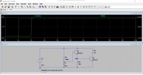
Here is a quick simulation showing the rail appearing at 1 second in and the final transistor turning on at 2 seconds in. So 1 second delay in a basic simulation.
Maybe the original cap wasn't all that good and the new cap is actually giving the correct delay.
It's a bit hard to work out exactly but around 1 second or less looks about right the more I look at it.
Here is a quick simulation showing the rail appearing at 1 second in and the final transistor turning on at 2 seconds in. So 1 second delay in a basic simulation.
Attachments
- Status
- This old topic is closed. If you want to reopen this topic, contact a moderator using the "Report Post" button.
- Home
- Amplifiers
- Solid State
- Relay timing