Ok Rayma - will get started on the diodes and resistors shortly and thank you very much for the guidance by the way
Are these semi's ok too ? - they just seem a bit low compared to the rest :
q607 was B to C .665 and B to E .178 *** (A1016)
q608 was B to C .667 and B to E .177 *** (A1016)
q616 B to C was .003 and B to E was .633 *** (D600K)
And we have one of the .22 emitter resistors reading @ 2.8
Are these semi's ok too ? - they just seem a bit low compared to the rest :
q607 was B to C .665 and B to E .178 *** (A1016)
q608 was B to C .667 and B to E .177 *** (A1016)
q616 B to C was .003 and B to E was .633 *** (D600K)
And we have one of the .22 emitter resistors reading @ 2.8
we have one of the .22 emitter resistors reading @ 2.8
For now we are looking for defective parts. Those semis seem ok, maybe the resistor is off but it will not cause the problems you see. Eventually you may remove and check the emitter resistor out of circuit and replace if off tolerance,
but not right now.
Hi Rayma, here are the 4 x 1n4148 Zenner Diode results
Check done with DVM on 'Diode' mode and diodes in circuit, amp unplugged
D601 + lead on Cath : 2.802
- lead on Cath : .626
D602 + lead on Cath : 2.810
- lead on Cath : .628
D603 + lead on Cath : 2.801
- lead on Cath : .635
D604 + lead on Cath : 2.800
- lead on Cath : .634
D901 + lead on Cath : 1.87
- lead on Cath : .638
D902 + lead on Cath : 2.65
- lead on Cath : .732
Will carry on with the resister checks now - all 85 of them, yikes...
Last edited:
Ok - checked all resistors, most in spec but a few came up lower than spec, some very low and some with zero, see below
R518 spec 8.25 testing = 3.78
R521 spec 33.3 testing = 26.0
R522 spec 33.2 testing = 26.0
R525 spec 100k testing = 34.4
R526 spec 100k testing = 35.5
R624 spec 33.2 testing = 9.7
R629 OL
R633 spec 33.2 testing = 0 got beep from dvm when I did continuity check
R634 spec 33.2 testing = 0 as above
There are two resistors which are notated on the PCB diagram but not in the parts list or the circuit diagram. The are printed with 10 ohm and '38 m', are all over buff colour but have no coloured rings. They're dimensions are 12mm long by 4.25mm in dia. They seem to bridge the + and - for each of the left and right channel speaker outs circuitry. (they tested ok at just over 10 ohms each) I'll take a photo and see if I can upload it.
Sorry, no go on the photo - when I click the insert image button, it's asking for a HTTP address.
Maybe my delightful description of the resistors might be enough
R629 OL
R633 spec 33.2 testing = 0
R634 spec 33.2 testing = 0
R633 and R634 are ok, they're just in parallel with the output fuses.
R629 is crucial to operation, it should be 0.22 ohms. Check it again.
What about R630, R631, R632 (which are the same value)?
Hi Rayma - if you don't mind me asking - can you tell me why the fuses need the R633 and R634 resitors ? and why it's ok if I get a bleep when checking in those two resistors continuity mode ? I check many other resistors and they don't bleep when dvm is in continuity mode. Thank you.
I rechecked R633 and R634 and got 00.66 and 00.62 respectively. Should be 33.2
Emitter resistors recheck results :
R629 OL
R631 .69
R632 .65
R630 .67
Before doing the check I sanded the component legs to make sure was getting good contact
I rechecked R633 and R634 and got 00.66 and 00.62 respectively. Should be 33.2
Emitter resistors recheck results :
R629 OL
R631 .69
R632 .65
R630 .67
Before doing the check I sanded the component legs to make sure was getting good contact
Last edited:
why the fuses need the R633 and R634 resitors ? and why it's ok if I get a bleep when checking in those two resistors continuity mode ?
Emitter resistors recheck results :
R629 OL
R631 .69
R632 .65
R630 .67
The fuses are in parallel with the resistors, and "short them out".
They are there to allow a low volume of audio after the fuse blows to remind you to replace the fuse.
Looks like those resistors will all need replacement, so start making a list.
is that it for the testing ? or will I do the list before the next thing?
There are a few electrolytic capacitors in the power amp circuit, but those are best just replaced
with similar ones regardless, when you order the other parts.
Problems can also be caused by non-component reasons, like bad connections, broken pcb traces,
bad solder joints, etc. Usually you can find those by careful visual inspection. You can do that while
waiting on the parts order to arrive.
Not sure if I do it correctly (posting a picture), but try clicking on the little 'attachment paper clip' along the top of the Advanced window. Then it gives a ten-or-so row box toward the upper left and you can Browse your local hard drive. Once you've picked the one(s) you want you can click Upload and close the box.
Regards
Regards
Rayma - fantastic, I'll do close inspection of solder connection and tracks. I'll make a list and order the resisters and capacitors although I do have a wee stock of both but not the emitter resisters, I'll definitely have to order them.
I'll keep you posted. Should only take a few days for delivery if I order the parts tomorrow. Thank you.
Rick, thanks for the information - I'll try that when I have problems with my next project and need advice. Note - I said 'when' I have problems, not 'if' lol.
I'll keep you posted. Should only take a few days for delivery if I order the parts tomorrow. Thank you.
Rick, thanks for the information - I'll try that when I have problems with my next project and need advice. Note - I said 'when' I have problems, not 'if' lol.
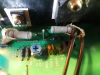
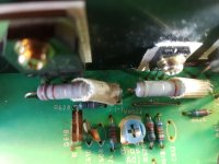
Sorry Rayma - before I order - the emitter resistors, is there any physical difference between them and normal resistors. The ones on the Rotel look like normal resistors with the coloured value rings but a bit larger than the other resisters on the PCB.
It's just in case I recive ordinary resistors, albeit of the required value, when I should have ordered proper 'emitter' ones.
Thank you sir
It's just in case I recive ordinary resistors, albeit of the required value, when I should have ordered proper 'emitter' ones.
Thank you sir
the emitter resistors, is there any physical difference between them and normal resistors.
Usually they are wire wound but can be metal oxide, etc. Can you post close photos of them?
HI Rayma,
I used Rick PA Stadel's method for uploading pics, hope it works here goes -
Those are metal oxide types. Get a wattage that is the same or larger physical size.
Will order this evening.
Those are likely to be 2W or 3W resistors, order the same physical size or larger.
- Status
- This old topic is closed. If you want to reopen this topic, contact a moderator using the "Report Post" button.
- Home
- Amplifiers
- Solid State
- Hifi amp signal flow question