Hi all, I'm posting this in hope that any of our members is familiar with the Harman Kardon Citation 11 preamp circuits, and can give me some advice.
I'm a novice with experience building kits from Dynaco in the 70's and lately from updatemydynaco.com to upgrade my Dynaco gear. So that's the extent of my abilities, I can follow instructions! My knowledge level in circuit diagrams and electrical theory and troubleshooting electrical circuitry is very limited. At the moment, I'm trying to solve a problem with the EQ section of my HK Cit 11.
The 60hz slider works on one channel & not the other. The other sliders (320, 1K, 5K & 12K) work fine on both channels. The Cit 11 has individual EQ boards for each channel, making it easy to spot any problems between one board & the other.
The parts list calls for a 1H 10% choke. No other specs are listed.
I checked resistance across the inductors on each board for each of the sliders and the value for the choke tied to the 60hz sliders measured .452K ohms on one and 14.02M ohms on the other.
I'm not sure which is the correct value, but judging from the values I measured across the other sliders, maybe it's the board that measured only 14.02m ohms. For example the 320hz sliders measure 321.5 ohms on one board, and 318 ohms on the other, the 1Khz sliders measured 97.1 ohms on one 96.4 ohms on the other. That's my thinking...
I pulled off the covers that shield the choke assemblies and looked at the chokes and they seemed fine, I unsoldered the choke that was reading 14.02m ohms and measured across its leads, and now get 0 reading. making me think that the heat from the iron finally made it fail.
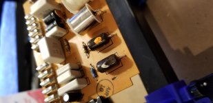
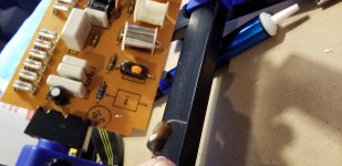
I've searched online for 1H chokes, and come up with nothing even close to what HK installed. I attach pictures for reference. I'm not sure if any other specs can be gleaned from the circuit diagram that I need to be looking for, but typing in "1H" and 1000mH" inductors on the various parts websites doesn't return anything I feel I can order confidently as a substitute for the original.
Visually, the choke is about 3/4" long, about 3/8" in diameter and covered in a waxy plastic. An interesting note is the space occupied by the 1H choke is labelled 1.4H on the board diagram! But it seems the boards in the 11 have many such mis-labelings so I'm not too concerned. Maybe I should be?
I'm wondering if any members who are more technically knowledgeable than I could steer me to a modern day equivalent.
Thanks in advance for any assistance!
I'm a novice with experience building kits from Dynaco in the 70's and lately from updatemydynaco.com to upgrade my Dynaco gear. So that's the extent of my abilities, I can follow instructions! My knowledge level in circuit diagrams and electrical theory and troubleshooting electrical circuitry is very limited. At the moment, I'm trying to solve a problem with the EQ section of my HK Cit 11.
The 60hz slider works on one channel & not the other. The other sliders (320, 1K, 5K & 12K) work fine on both channels. The Cit 11 has individual EQ boards for each channel, making it easy to spot any problems between one board & the other.
The parts list calls for a 1H 10% choke. No other specs are listed.
I checked resistance across the inductors on each board for each of the sliders and the value for the choke tied to the 60hz sliders measured .452K ohms on one and 14.02M ohms on the other.
I'm not sure which is the correct value, but judging from the values I measured across the other sliders, maybe it's the board that measured only 14.02m ohms. For example the 320hz sliders measure 321.5 ohms on one board, and 318 ohms on the other, the 1Khz sliders measured 97.1 ohms on one 96.4 ohms on the other. That's my thinking...
I pulled off the covers that shield the choke assemblies and looked at the chokes and they seemed fine, I unsoldered the choke that was reading 14.02m ohms and measured across its leads, and now get 0 reading. making me think that the heat from the iron finally made it fail.
I've searched online for 1H chokes, and come up with nothing even close to what HK installed. I attach pictures for reference. I'm not sure if any other specs can be gleaned from the circuit diagram that I need to be looking for, but typing in "1H" and 1000mH" inductors on the various parts websites doesn't return anything I feel I can order confidently as a substitute for the original.
Visually, the choke is about 3/4" long, about 3/8" in diameter and covered in a waxy plastic. An interesting note is the space occupied by the 1H choke is labelled 1.4H on the board diagram! But it seems the boards in the 11 have many such mis-labelings so I'm not too concerned. Maybe I should be?
I'm wondering if any members who are more technically knowledgeable than I could steer me to a modern day equivalent.
Thanks in advance for any assistance!
Attachments
Next Steps
Test the DC resistance of each of the 1 Henry inductors separately. To do this, you'll have to lift one leg of the inductor to get a blameless DC resistance reading. I would guess that such an inductor would have about 300-400 Ohms of DC resistance.
To avoid ambiguity, when you report the results, spell out milli or Mega with the Ohms readings, as just saying m-ohms is quite ambiguous.
Dan, again, thanks for your help. These are the readings I took for DC resistance:
The 1 Henry inductor on the "bad" board now measures 0.0, I feel I damaged it when I removed it.
Before I removed it I got a reading of 14.02 M ohms as displayed on the multimeter, but now after reading your reply regarding the ambiguity, I'm not sure if that was mega, milli or even micro ohms. So the reading could have been 1.4 ohms, or 14 ohms or even 140 ohms.
The 1 Henry inductor on the "good" board reads 442 ohms, just as you expected.
In any case, it seems to be out of spec compared to the good board.
If it helps, here are the readings for the other inductors:
Good board: 315.7, 95.9, 30.2, 21.5 all in ohms
Bad board: 321.3, 98.4, 31.6, 23.1 all in ohms
So for the rest of the EQ sliders, the DC resistance values are very close, the only out-of-whack one is the resistance for the 1 Henry inductor on the bad board that goes to the 60 Hz slider.
Last edited:
Inductors are coils of wire so the DC resistance measurement should be quite low. To get 1 H is going to require a lot (many turns) of very fine wire which will give you some resistance maybe tens to hundreds of ohms.
I wouldn't expect the inductor itself to go bad, they usually don't have an aging mechanism like capacitors. Look for wire breaks or bad solder joints.
tommost
I wouldn't expect the inductor itself to go bad, they usually don't have an aging mechanism like capacitors. Look for wire breaks or bad solder joints.
tommost
Last edited:
Bad inductors
Tom, thanks for your reply.
I also thought inductors wouldn't go bad, since like you explain they're just coils of wire around a core. But on that "bad" 1 H inductor, I now get no resistance across the terminals whether the inductor is on the board, with 1 lead off the board, or out of the board completely. So maybe something went wrong with it, maybe a broken connection inside it?
Ernie
I'm still a little confused...what is the "bad" inductor resistance with one (or both) ends lifted out of the circuit?
If it's infinite...then there's an open...and it must be replaced.
If it's much less than 400 Ohms, then there are shorted turns, and it must be replaced.
Finally...you could determine if it's the only problem by swapping the good inductor to the bad side.
Once we know for sure about the status of the inductor, we can go about finding or making a replacement.
High value inductors have very thin wire, and this is less than robust, especially as the core is relatively heavy - its important the core is anchored down securely and the strain taken off the fine wire (i.e. its not taut).
Otherwise if the unit gets bashed/dropped the fine wire is likely to break or be stretched, as likely happened here.
Otherwise if the unit gets bashed/dropped the fine wire is likely to break or be stretched, as likely happened here.
Confirmed 1 H inductor is bad
Dan, I did as you suggested and swapped the good inductor to the bad side. The bad side now works.
I imagine this means I have a bad inductor, and like you explain it would have to be replaced or built.
I have found a 900 millihenry inductor at Mouser, it's called a telecoil, meant for use in hearing aids. It's Knowles part 5100-253444. These are in stock.
I attach the pdf. It's small appx. 9mm X 2.3mm, 15% tolerance. It's the closest I have found anywhere to the 1 H value.
Knowles also makes a 520 millihenry inductor, also 15% tolerance, part 5100-253144. I attach the spec sheet for it too.I am wondering whether 2 wired in series would achieve 1.04 H, closer to the original HK spec.
However I am not sure how suitable either part would be as a replacement for the original part.
Maybe you can give me your thoughts, and advise how to proceed.
I'm still a little confused...what is the "bad" inductor resistance with one (or both) ends lifted out of the circuit?
If it's infinite...then there's an open...and it must be replaced.
If it's much less than 400 Ohms, then there are shorted turns, and it must be replaced.
Finally...you could determine if it's the only problem by swapping the good inductor to the bad side.
Once we know for sure about the status of the inductor, we can go about finding or making a replacement.
Dan, I did as you suggested and swapped the good inductor to the bad side. The bad side now works.
I imagine this means I have a bad inductor, and like you explain it would have to be replaced or built.
I have found a 900 millihenry inductor at Mouser, it's called a telecoil, meant for use in hearing aids. It's Knowles part 5100-253444. These are in stock.
I attach the pdf. It's small appx. 9mm X 2.3mm, 15% tolerance. It's the closest I have found anywhere to the 1 H value.
Knowles also makes a 520 millihenry inductor, also 15% tolerance, part 5100-253144. I attach the spec sheet for it too.I am wondering whether 2 wired in series would achieve 1.04 H, closer to the original HK spec.
However I am not sure how suitable either part would be as a replacement for the original part.
Maybe you can give me your thoughts, and advise how to proceed.
Attachments
Good searching, but the DC resistance of both inductors looks kind of high...I don't think they are good replacements.
Your existing inductor must have a shorted turn or turns, thus the low DCR.
I'm doing a little looking around...I may have an answer for you tomorrow, with a bit of luck. If no luck, we might be able to do an active inductor as a replacement.
Your existing inductor must have a shorted turn or turns, thus the low DCR.
I'm doing a little looking around...I may have an answer for you tomorrow, with a bit of luck. If no luck, we might be able to do an active inductor as a replacement.
Problem fixed, thanks to Dan Joffe of updatemydynaco.com and akitika.com
After troubleshooting the issue and by process of elimination concluding that the fault lay in a bad 1H inductor, I thank Dan for his assistance with the diagnosis. Thanks Dan!!
Now finding a 1H inductor of the right type and size out in the open market of electronic component parts, was fruitless. They do not exist!
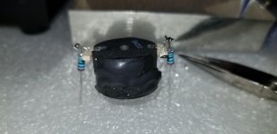
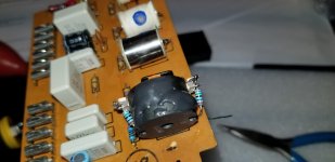
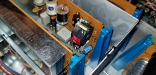
Dan custom wound a pot core inductor for me, which along with 2 150 ohm resistors provided the correct value to operate the circuit. I attach a few photos of the build, showing the inductor assembly on the board. Dan very wisely included an installation and assembly diagram.
The circuit now works as per original spec, and there's no audible difference between the original board with the HK factory inductor and the side with Dan's.
So I'm a happy camper again, can now boost the low end with the 60Hz slider operating on both channels. Very useful as I attempt to re-create a loudness curve in my office system playing back at at low volume levels.
So, thanks Dan, you're a gentleman and a scholar, and a hell of an audio engineer!
After troubleshooting the issue and by process of elimination concluding that the fault lay in a bad 1H inductor, I thank Dan for his assistance with the diagnosis. Thanks Dan!!
Now finding a 1H inductor of the right type and size out in the open market of electronic component parts, was fruitless. They do not exist!
Dan custom wound a pot core inductor for me, which along with 2 150 ohm resistors provided the correct value to operate the circuit. I attach a few photos of the build, showing the inductor assembly on the board. Dan very wisely included an installation and assembly diagram.
The circuit now works as per original spec, and there's no audible difference between the original board with the HK factory inductor and the side with Dan's.
So I'm a happy camper again, can now boost the low end with the 60Hz slider operating on both channels. Very useful as I attempt to re-create a loudness curve in my office system playing back at at low volume levels.
So, thanks Dan, you're a gentleman and a scholar, and a hell of an audio engineer!
Attachments
- Status
- This old topic is closed. If you want to reopen this topic, contact a moderator using the "Report Post" button.
- Home
- Amplifiers
- Solid State
- Harman Kardon Citation 11 preamp EQ board question