Have you got the class A switch operated . Just trying to work out where the extra current is going . Also switch both speaker selection switches off .
Ps I calculated the idle current with no relays operating .
No, class A is not activated and no speaker switches.
Checked all transistors - cant find any shorts or opens. All checks out around the .65V
How about trying with the equivalent of a 100W bulb in the limiter .
I could do that, but I'm inclined to wait for a bit. I am currently waiting on some new electrolytic caps, and think I want to replace them before moving on.
I desoldered C711 and C712 and did a series of tests. Altough I don't have the best methods for testing, I concluded that they behave different and one does not seem to hold even a small charge for any period of time
Last edited:
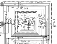
While you are at it check/change CN06 ( bottom right amp schematic ) , another electrolytic with virtually nil polarising voltage . I would change it to a non polarised electrolytic . I mentioned it back in post 24 but only as a suspect when you were dealing with the volume related protection triggering .
Last edited:
ESR .co.uk
Don't you have a Farnell in Norway ?
Yes, but seems to me most of the stock is in England anyways
All I can say is it would be my preference but it was built with a polarised and it is fed AC through two 68K resistors which will limit any leakage current .
Had a quick read about this, and I see your point. But would this not apply to C711 and C712 as well, or are these somewhat protected by the RC filter?
Nearly , C711 and C712 have a +0.65V polarising voltage across them where as CN06 does not .
PS most amplifiers will use a polarised capacitor in C711 and C712 often with a reverse polarised diode across them to limit a potential reverse polarity fault voltage to 0.65V
PS most amplifiers will use a polarised capacitor in C711 and C712 often with a reverse polarised diode across them to limit a potential reverse polarity fault voltage to 0.65V
Last edited:
Nearly , C711 and C712 have a +0.65V polarising voltage across them where as CN06 does not .
PS most amplifiers will use a polarised capacitor in C711 and C712 often with a reverse polarised diode across them to limit a potential reverse polarity fault voltage to 0.65V
Correction..... C711 and C712 will have a minimal - 0.3V across them not as I previously wrote so very slightly reverse polarised ( as long as the actual board agrees with the schematic ) therefore on reflection I think they would also benefit from being non polarised , my apologies . Watch out for the pitch of the pins with replacement caps . No other caps stand out for me as candidates for replacing with non polarised .
Last edited:
Correction..... C711 and C712 will have a minimal - 0.3V across them not as I previously wrote so very slightly reverse polarised ( as long as the actual board agrees with the schematic ) therefore on reflection I think they would also benefit from being non polarised , my apologies . Watch out for the pitch of the pins with replacement caps . No other caps stand out for me as candidates for replacing with non polarised .
Yeah, I was studying the schematic and could not work out where that value you stated first would come from. Thank you for clarifying.
I will probably test the amp with the new polarized caps first, then order non polarized if things seem to be working
Update: Changed all electrolytic caps on P701 board and had a new go at powering up - same behavior. Pulsating glow in bulb limiter, power LED's on P701 pulsating in same pattern but dims. Very stable frequency of pulsing
After some contemplating I just could not believe what could be wrong with the amp board now, so I went ahead and pulled away J701 to isolate the rest of the boards from P701
Lo and behold - protection relay clicked on and I can operate speaker relays. Measured DC offset to -0.03V on L and 0V on R at center pin on emitter resistors. Next I plugged in J701 and disconnected J502 on volume/preamp board P501. This is as far as I got now. There is something going on with P501, and I am breaking it out to inspect

- 18V rail . Lets hope it has not affected any of the transistors on that board
PS good news on the main amp board")
Yes, I have my fingers crossed for the transistors. There's a few pairs of FET's on the circuit. Would these measure with the same values as the rest of the transistors?
Feels a bit more relaxed with the main amp board now, finally
There's a few pairs of FET's on the circuit. Would these measure with the same values as the rest of the transistors?
Gate to Source and gate to Drain yes the same , Source to Drain will be a low resistance both ways .
Gate to Source and gate to Drain yes the same , Source to Drain will be a low resistance both ways .
Thanks! Good to know

- Status
- This old topic is closed. If you want to reopen this topic, contact a moderator using the "Report Post" button.
- Home
- Amplifiers
- Solid State
- Marantz PM-80mkII issues (I'm sorta stuck)