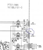
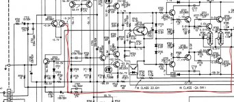
Both schematics I have both have an earth ground coming in from the right hand side of the board . Does your board have 3 protection relays on the output/speaker side as my other schematic only has 2 .
My board has 3 relays - LN03, 04 and 05
Yes with 3 relays it does not appear to be an SE board , however it has the different biasing resistors of an SE .
With all the board plugs inserted you should still see an earth/ground on the bottom ends of RN01 and RN02 , both 22K , which ever schematic is relevant .
PS your second post shows a 3 relay schematic .
With all the board plugs inserted you should still see an earth/ground on the bottom ends of RN01 and RN02 , both 22K , which ever schematic is relevant .
PS your second post shows a 3 relay schematic .
PS your second post shows a 3 relay schematic .
Correction …. first post .
As the current (undiagnosed) fault is common to both channels, look for components common to both channels.R755: -17,5V
R757: -21V
R756: -17,2V
R758: -20V
Please measure the voltages (referenced to 0V/Gnd) on both sides of the resistors marked in RED.

Also, please confirm the current configuration of the amplifier: i.e. Is it complete? What parts/(problems) have been introduced?
Pictures are a good source of information (a picture is worth a thousand words)!
Whilst troubleshooting/fault-finding, NEVER engage Class A mode (unless requested to do so). Keep the volume control @ ZERO/minimum.
Good Luck!
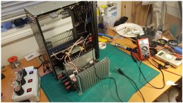
P.S. Nice build on the bulb limiter.
Addendum: The circuit diagrams in the service manuals may contain errors.
Last edited:
Correction …. first post .
You're right. My first post is from the MKII manual, wich seems to correspond to my board, except from the SE bias resistor values, and the fact that my board has the SE serial number
So I found the reason for the missing ground on P701/J704 and 705
I did testing with the whole power amp part out from the chassis, and thereby missed the grounding via two screws at the speaker terminals. They look like plastic but has a connection internally
I thought I was good by adding a jumper between chassis and ground strap on cooling fin - but no.
After adding the missing ground, the amp behaves very different. Sort of pulsing glow in the bulb and power indicators. Shot a video to illustrate. Makes it somewhat hard to do voltage readings when it acts like this though.
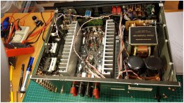
State of amp as of now are complete minus one pair of power transistors pr. channel - Q731, Q733 and Q732, Q734
Video: YouTube
I did testing with the whole power amp part out from the chassis, and thereby missed the grounding via two screws at the speaker terminals. They look like plastic but has a connection internally
I thought I was good by adding a jumper between chassis and ground strap on cooling fin - but no.
After adding the missing ground, the amp behaves very different. Sort of pulsing glow in the bulb and power indicators. Shot a video to illustrate. Makes it somewhat hard to do voltage readings when it acts like this though.
State of amp as of now are complete minus one pair of power transistors pr. channel - Q731, Q733 and Q732, Q734
Video: YouTube
Attachments
Is the same happening between pins 1 and 2 J704.
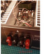
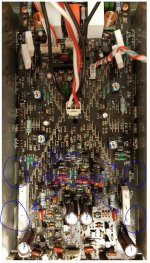
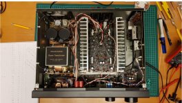
Would you post a photo of the whole of your amp taken from above so that we can see where all the boards are located .
PS have you got all the biasing preset resistors set for minimum bias .
Yes, same on pin 1 and 2
Yes, Bias pots is set to minimum
Attachments
So, I have a few things I would like try but would apreciate if you guys could confirm if this is a good idea, or advice against if it sounds bad
Since J704 more or less only feeds power transistors with rail voltages, and there is no direct short between pins with power off, I have a theory that the low voltages is due to the power transistors beeing always "on" creating a near short when power is on - maybe corealated to the burnt power transistors and emitter resistor from before.
I want to disconnect J704 and power the amp up to see if I can take some more voltage measurements to see if something deeper in the circuit is creating a - what would one call it? - "fake" bias way above the intended values. Apologies for my possibly stumbling way of explaining. Combined lack of experience and language barrier
Yes that's the path I am on about .
Using the 60W bulb in series with the amp I have calculated that the amp should settle down with 64% of the 240V mains therefore the rails should be at 64% of 56V which is approx. 36V , which is about what you had when you were powering it up with the amp board out on the bench , but at that point the input transistors were not being biased because there was no earth/ground feed to the transformer centre tap .
What voltages do you have on the amp outputs prior to the relay contacts . I know they could be jumping around .
Last edited:
Yes that's the path I am on about .
Using the 60W bulb in series with the amp I have calculated that the amp should settle down with 64% of the 240V mains therefore the rails should be at 64% of 56V which is approx. 36V , which is about what you had when you were powering it up with the amp board out on the bench , but at that point the input transistors were not being biased because there was no earth/ground feed to the transformer centre tap .
What voltages do you have on the amp outputs prior to the relay contacts . I know they could be jumping around .
I measured not more than half a volt, both positive and neg. Fluctuating a lot though, but in a seemingly stable patern
Last edited:
I think it would be worth going over all the transistor junctions again with the diode test ( with the power off ) .
Ok, I did yesterday on the power transistors. Those checked out fine I think.
I measured not more than half a volt, both positive and neg. Fluctuating a lot though, but in a seemingly stable pattern
That's a glimmer of light at the end of a tunnel .
- Status
- This old topic is closed. If you want to reopen this topic, contact a moderator using the "Report Post" button.
- Home
- Amplifiers
- Solid State
- Marantz PM-80mkII issues (I'm sorta stuck)