Hi Shaun, as you mention high speed and precision grounding demand totally approaches. For audio, the former is totally out of scope given the frequencies we are dealing with. Besides the basics, I am no expert on ultra high speed design. The highest speed design I did was ~1Ghz, a high speed ADC driver. But yes, ground planes are common practice in high speed design.
Surprisingly (or maybe not) audio and precision applications share a lot in common. Mostly because distortion is nothing more than non-linear, signal dependent off-sets, and noise is a random time-varying offset. Grounding is no exception.
For audio amplifiers, the things I think about are as follows:
1. What are signals referred to
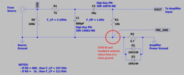
You always want signals that related to be referenced to the same ground. For example, in my previous post I mentioned that you want the DC defining resistor at the non-inverting input of the amplifier and the feedback network to be referenced to same ground, and their connections to be starred to it. This way ground noise becomes common mode and rejected by the amplifier's CMRR.
2. Which grounds are clean (namely the signal grounds) and which ones will exhibit ground bounces (power grounds).
In audio power amplifiers, the power supply and the speaker return line will inject large currents to the ground, hence that ground will exhibit substantial ground bounce. As you mention, this is our power ground. The ground coming from the source in the connector should be a clean signal ground. If ground bounce gets into the signal circuit, it will show at the output as either distortion, pops, hum, etc.
If we follow the suggestion from 1, technically ground bounce should not be an issue, but as Federico pointed out, it is a good idea to connect your inputs to the clean ground to give you a further safety net (maybe we have an amp with bad CMRR).
3. Where are currents being returned
The ones to watch out are large power currents from the supply and the speaker return line which have substantial noise. You really don't want these to return to the source via the input jack since you will forming a ground loop. This is bad because for one you are creating a loop antenna which will induce pickup, and for two, through mutual inductance you are coupling the noisy current into your input line. To fix this, we add the 4.7 ohm decoupling resistor between the source (signal) and the power ground.
Finally, since we are dealing with a single ended system, all lines to the power ground should be starred (including the signal ground through the 4.7 ohm resistor) to provide a common reference point. This is because the amplifier output is actually also referred to the signal ground since we have a single ended output, but because of 3, we cannot connect the speaker return line to the signal ground. So starring is the next best thing to keep all the references common.
Anyway, this post ended up being longer than I thought, but I hope it puts out some key ideas regarding grounding. Regarding the circuit, I am going to keep it as in v2, with a reminder that the feedback network needs to star to resistor R2 ground connection.
Best, Sandro
Surprisingly (or maybe not) audio and precision applications share a lot in common. Mostly because distortion is nothing more than non-linear, signal dependent off-sets, and noise is a random time-varying offset. Grounding is no exception.
For audio amplifiers, the things I think about are as follows:
1. What are signals referred to
You always want signals that related to be referenced to the same ground. For example, in my previous post I mentioned that you want the DC defining resistor at the non-inverting input of the amplifier and the feedback network to be referenced to same ground, and their connections to be starred to it. This way ground noise becomes common mode and rejected by the amplifier's CMRR.
2. Which grounds are clean (namely the signal grounds) and which ones will exhibit ground bounces (power grounds).
In audio power amplifiers, the power supply and the speaker return line will inject large currents to the ground, hence that ground will exhibit substantial ground bounce. As you mention, this is our power ground. The ground coming from the source in the connector should be a clean signal ground. If ground bounce gets into the signal circuit, it will show at the output as either distortion, pops, hum, etc.
If we follow the suggestion from 1, technically ground bounce should not be an issue, but as Federico pointed out, it is a good idea to connect your inputs to the clean ground to give you a further safety net (maybe we have an amp with bad CMRR).
3. Where are currents being returned
The ones to watch out are large power currents from the supply and the speaker return line which have substantial noise. You really don't want these to return to the source via the input jack since you will forming a ground loop. This is bad because for one you are creating a loop antenna which will induce pickup, and for two, through mutual inductance you are coupling the noisy current into your input line. To fix this, we add the 4.7 ohm decoupling resistor between the source (signal) and the power ground.
Finally, since we are dealing with a single ended system, all lines to the power ground should be starred (including the signal ground through the 4.7 ohm resistor) to provide a common reference point. This is because the amplifier output is actually also referred to the signal ground since we have a single ended output, but because of 3, we cannot connect the speaker return line to the signal ground. So starring is the next best thing to keep all the references common.
Anyway, this post ended up being longer than I thought, but I hope it puts out some key ideas regarding grounding. Regarding the circuit, I am going to keep it as in v2, with a reminder that the feedback network needs to star to resistor R2 ground connection.
Best, Sandro
Quick update: V2 is of the schematic is the way to go.
Quick update:
I just realized I made a terrible mistake in one of my comments above .
.
Tying the input resistor R2 and the feedback network to the same reference WILL NOT reject the ground noise, it will only reduce its gain to 1 (rather than get amplified by the closed loop gain). I am really sorry for stating non-sense. My mind was on 4 resistor subtractors where this is the case.
In any case, we do want want to do the following:
- Tie resistor R2 and feedback network return points together to a clean ground to minimize ground noise gain (reduce it to unity).
- Separate amplifier power ground from signal ground with a decoupling resistor.
- Star power ground as much as possible.
Sorry again for the misinformation.
Best, Sandro
Quick update:
I just realized I made a terrible mistake in one of my comments above
.Tying the input resistor R2 and the feedback network to the same reference WILL NOT reject the ground noise, it will only reduce its gain to 1 (rather than get amplified by the closed loop gain). I am really sorry for stating non-sense. My mind was on 4 resistor subtractors where this is the case.
In any case, we do want want to do the following:
- Tie resistor R2 and feedback network return points together to a clean ground to minimize ground noise gain (reduce it to unity).
- Separate amplifier power ground from signal ground with a decoupling resistor.
- Star power ground as much as possible.
Sorry again for the misinformation.
Best, Sandro
Attachments
Last edited:
3.2. Audio Amplifier Design Fundamentals: Measuring Loop gain and Open loop gain, dem
Hi all, just to let you know that I just uploaded the next video of the series:
3.2. Audio Amplifier Design Fundamentals: Measuring Loop gain and Open loop gain, demo in LTSpice
The materials associated with the video are in the attachment.
Enjoy,
Sandro (SW Audio)
Hi all, just to let you know that I just uploaded the next video of the series:
3.2. Audio Amplifier Design Fundamentals: Measuring Loop gain and Open loop gain, demo in LTSpice
The materials associated with the video are in the attachment.
Enjoy,
Sandro (SW Audio)
Attachments
Hi all, just to let you know that I just uploaded the next video of the series:
3.2. Audio Amplifier Design Fundamentals: Measuring Loop gain and Open loop gain, demo in LTSpice
The materials associated with the video are in the attachment.
Enjoy,
Sandro (SW Audio)
As always, any feedback is highly welcomed!
Hi Gannaji, you are right, that blue color is difficult to work with.
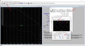
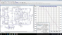
Here is a solution (see the attached image):
+ Click the hammer button on the toolbar and select the 'Waveforms' tab
+ Click on color scheme
+ Change the color scheme of V(2) by either:
- Swapping the blue of V(2) with the Greenish/Yellowish of V(12) by dialing the RED, GREEN, BLUE numbers. I.e. Change V(2) to R:175, G:175, B:0 and V(12) to R:0, G:0, B:255).
- OR -
- Changing V(2) to a new color. I am going with this route for now and setting V(2) to R:200, G:200, B:255. Its a purplish white which is more visible. [See image]
+Click OK.
That should do it.
Let me know if you have other questions.
Best, Sandro
Attachments
Hi Gannaji, you are right, that blue color is difficult to work with.
Here is a solution (see the attached image):
+ Click the hammer button on the toolbar and select the 'Waveforms' tab
+ Click on color scheme
+ Change the color scheme of V(2) by either:
- Swapping the blue of V(2) with the Greenish/Yellowish of V(12) by dialing the RED, GREEN, BLUE numbers. I.e. Change V(2) to R:175, G:175, B:0 and V(12) to R:0, G:0, B:255).
- OR -
- Changing V(2) to a new color. I am going with this route for now and setting V(2) to R:200, G:200, B:255. Its a purplish white which is more visible. [See image]
+Click OK.
That should do it.
Let me know if you have other questions.
Best, Sandro
Just change background color to white.
BR Damir
Wow dear Damir! An easier solution !
--gannaji
Indeed, but only if you like a white a background
") .
.The program I used at ADI for years only allowed for black background, so I am too used to it to change.
Indeed, but only if you like a white a background
The program I used at ADI for years only allowed for black background, so I am too used to it to change.
Black background sounds very strange to me. Do you read books on black paper with color characters? Printing black background will spend much more ink or toner.
Hi Damir, when you are looking at schematics and plots all day day on a screen, looking at a white background will tire your eyes. White paper is fine because unlike a screen, paper does not produce light, it simply reflects it and is less tiring on your eyes.
Also, I think the black background, given the elevated contrast, allows you to pick small details better. For example, if you miss-wired something, you can see it faster on a black background, or if you see a blip in a plot (blip being whatever you want).
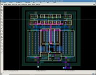
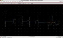
The attached screenshot is of the Cadence design suite which is pretty much used by everyone is industry. Note the black backgrounds on schematics, plots and layouts.
Interestingly, even though the schematics, plots and layouts are on a black screen, everything was printed with white backgrounds (save toner).
PS. The schematic and plot are Cadence 6, the layout is Cadence 5.
Also, I think the black background, given the elevated contrast, allows you to pick small details better. For example, if you miss-wired something, you can see it faster on a black background, or if you see a blip in a plot (blip being whatever you want).
The attached screenshot is of the Cadence design suite which is pretty much used by everyone is industry. Note the black backgrounds on schematics, plots and layouts.
Interestingly, even though the schematics, plots and layouts are on a black screen, everything was printed with white backgrounds (save toner).
PS. The schematic and plot are Cadence 6, the layout is Cadence 5.
Attachments
Last edited:
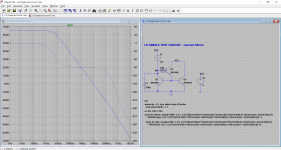
you are right. I think I am going to try to change the background of plots to something like the background color of schematics. That tombstone grey.
Best, Sandro
P.S. That is CFA 200W... great design.
That is 100W version.
I subscribed but don't know the number.
Hi dadod, I think this black background business is Cadence's fault, it is the default of their software and nobody ever changes it.
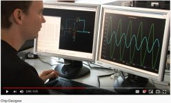
I stumbled on this German video (I did not understand a thing) in youtube about IC design, and as expected, the designer is: i. Using Cadence ii. Using black background
My setup at ADI was exactly the same as his... it brought back memories.
Oh well. I have used the grey background now for a couple days, I like it enough to keep it. Thanks for the pointer.
Best, Sandro
Video: YouTube
Attachments
Hi Sandro,
I watched the first two video’s, excellent, your ltspice test bench methodology is what I need to better use the simulator. I need to spend some time learning to use it to get more familiar with it.
What is the end goal? Is it making a working amplifier in an enclosure? If so, relay your thoughts for us following along on your journey.
Cheers
Rick
Hi Sandro,
excellent initiative, I am sure this will be helpful for many, I quickly checked through all 5 videos given in the first post, the video looks good, but let me cut to the chase, the audio quality has a bit too much room reverberation which is a sign the microphone is, for the given acoustics in your recording milieu, too far away, it would be much better if you have the microphone mounted on a boom arm and not more than about a foot away from your mouth, to get the idea how much better it can get check out the following video (which uses the same Samson Meteor microphone as you), go directly to 11:27 and compare that to other parts of the video when the microphone is standing on the desk (although his room seems to be better damped than yours so desk mounted still sounds better in his case).
YouTube - Samson Meteor Mic review (w/BONUS BLUE YETI sound comparison)
btw, I like the tinted background better than pure white, it is saving the eyes, it's actually not so much about taste but rather about eye health, LCD screens uses white LED background light which all have strong peak in the upper blue spectrum and is not good for the retina.
Cheers Michael
Actually a white LED is a Blue LED with a special phosphor covering it.
Thanks Sandrohv for the effort you put into the videos. I look forward to learning a lot from your efforts. I only wish that there was a Python interface to the LTSpice simulator. Keep up the GREAT work. Thanks
Thanks Sandrohv for the effort you put into the videos. I look forward to learning a lot from your efforts. I only wish that there was a Python interface to the LTSpice simulator. Keep up the GREAT work. Thanks
- Home
- Amplifiers
- Solid State
- SW-VFA-01: Audio power amplifier video series