So I'm finishing up repairing one channel on this amp. Replaced the lateral mosfets with Exicon To3 outputs. Also replaced a few drivers and resistors. For an extra step, I replaced the electrolytic caps. and adjustment trim pots, on both driver boards. I measured the settings of the trimmers and pre-set the new trimmers before installation.
Since it is not recommended to set the balance (distortion) adjustment from the manual, has anyone found any instructions on how to do the adjustment with an oscilloscope. and DMM.??
Since I replaced some critical parts on the driver section, I think that the balance adjust may need to be checked or changed. The original trim pot. setting for the repaired channel may not apply any more.
Thanks, Bill
They say you need a thd analyzer or a good sound sound card and software to adjust the balance. I'd leave to where it was set, unless you have the test equipment. a scope or dmm wont help you.
you do need to adjust the fet bias. They say use an ammeter in place of the fuse, adjust for 150mA of bias current.
You could also use a blown fuse and solder a 0.1 ohm resistor across it as your test shunt, measure the voltage drop across the 0.1 ohm * 150mA bias = 15mV, could use a 1 ohm as well for 150mV drop
Good luck happy mew year
I asked someone more knowledgeable than myself about the balance pot,
Hafler DH-200/220 Mods
Hafler DH-200/220 Mods
Hafler HD 120
Good morning
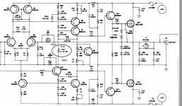
I'm building hafler HD120 I found a problem in the schematic the transistors Q6 eQ7 are NPN, on the component list are of the 2n 5401 PNP I assume that component list and schematic is original hafler
forgive my English, thank you for your attention
Fabrizio
Good morning
I'm building hafler HD120 I found a problem in the schematic the transistors Q6 eQ7 are NPN, on the component list are of the 2n 5401 PNP I assume that component list and schematic is original hafler
forgive my English, thank you for your attention
Fabrizio
DH-120 Schematic
You are correct. Go by the parts list.
An option is to download the Hafler Pro1200 manual, Same basic schematic improved.
The schematic is corrected.
Also note that R10 was increased to a 5 watt resistor. It gets hot!
Good Luck!
Good morning
I'm building hafler HD120 I found a problem in the schematic the transistors Q6 eQ7 are NPN, on the component list are of the 2n 5401 PNP I assume that component list and schematic is original hafler
forgive my English, thank you for your attention
Fabrizio
You are correct. Go by the parts list.
An option is to download the Hafler Pro1200 manual, Same basic schematic improved.
The schematic is corrected.
Also note that R10 was increased to a 5 watt resistor. It gets hot!
Good Luck!
This may have been answered, but what was the reasoning for R10 5.1K.
A departure from the basic DH-220 schematic. V drop across that thing is close to 100VDC. Started out as a 2W part and then bumped up to a 5W wirewound.
I think when I did mine I replaced it with about a 5W 1% resistor I had on hand...
The old 2W parts did a very good job of cooking the PCBs.
I got really unlucky with mine and had to set the balance pot since the original trimmer failed.
I just connected the amp up to an analyzer (you could use a decent sound card with an attenuator) and tweaked the balance and bias adjustment pots for the lowest distortion at 150mA current.
Now I just need to find time to troubleshoot the left channel. The amp works fine, but I'm still struggling to get the left channel to hold its bias (after like half hour of use, both heatsinks are warm. Two hours later, the thing still passes audio fine but the left heatsink is stone cold and the right one is appropriately warm.)
I wonder if your bias transistor has become thermally intermittent to an open condition or a cold solder joint that opens when the pcb warms up.
I replaced all the trimmer pots. with Bourns from Mouser and reset them duplicating the original resistance.
I also ended up paralleling 2 10K 2W resistors to upgrade R10.
The original Piher trimmers are pretty crusty by now. Good idea to replace them.
- Status
- This old topic is closed. If you want to reopen this topic, contact a moderator using the "Report Post" button.
- Home
- Amplifiers
- Solid State
- Repairing Hafler DH-120 Balance Adjustment