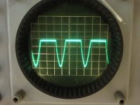
Hi, please, help me. I have Azur amplifier, one chanell is wrong. I send two pictures . Input signal goes to CN2. More input signal give more amplitude down but no up. The two tranzistors on the end are slightly warm. There is no speaker protection. (removed). Thank
Attachments
The Sanken SAP15N and SAP15P darlington output transistors have been obsolete for many years now, replaced by simpler devices (STD02, 03) that eliminate the troublesome internal emitter resistors. DIY replacement may still prove difficult and expensive unless you have some experience with power amplifier repairs and troubleshooting. Note, if mica insulators are fitted, they may be irreplaceable so take care with them.
Needless to say, this may have been inevitable when the protection circuit was removed. Unfortunately, Sanken power transitors around on Ebay etc. are mostly fakes. Don't deal with unauthorized sellers and don't take risks when they look like an easy option. The photos may be of genuine parts but yours will likely be different, if only slightly. Unless you have the time and cash to waste on fakes and the expertise to spot them before they cause more damage through repeated mounting and soldering etc, don't bother.
Needless to say, this may have been inevitable when the protection circuit was removed. Unfortunately, Sanken power transitors around on Ebay etc. are mostly fakes. Don't deal with unauthorized sellers and don't take risks when they look like an easy option. The photos may be of genuine parts but yours will likely be different, if only slightly. Unless you have the time and cash to waste on fakes and the expertise to spot them before they cause more damage through repeated mounting and soldering etc, don't bother.
Last edited:
Ok. Repair can take more month, perhaps handle it itself. With your help. I hope, i will buy this :
Cambridge Audio Azur 340A Integrated Amplifier | eBay
before. I need not great output watt performance.
Cambridge Audio Azur 340A Integrated Amplifier | eBay
before. I need not great output watt performance.
Measurement:
DCoffset: wrong channel 0,002 V, OK channel 0,056 Volt (multimeter, DC)
R 0,22 OK,,,R99 OK
pin 1 to 5 : 1,14 Volt both channels
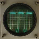
Note1: On the oscilloscope, the upper line stay on one position 0,5 Volt above default 0,0.
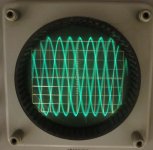
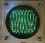
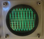
More input signal, more sinus Volt down.
Note2 : I buyed both tranzistors for repair previously, when it would be necessary. From England. Perhaps they are no fakes. But for me, can i hear the differences ? I need repair my amplifier. One trouble : I am not enought brave to rotate the main desk bottom up.
DCoffset: wrong channel 0,002 V, OK channel 0,056 Volt (multimeter, DC)
R 0,22 OK,,,R99 OK
pin 1 to 5 : 1,14 Volt both channels
Note1: On the oscilloscope, the upper line stay on one position 0,5 Volt above default 0,0.
More input signal, more sinus Volt down.
Note2 : I buyed both tranzistors for repair previously, when it would be necessary. From England. Perhaps they are no fakes. But for me, can i hear the differences ? I need repair my amplifier. One trouble : I am not enought brave to rotate the main desk bottom up.
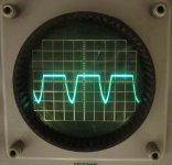
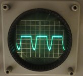
Any pictures : Note: R70 (good channel) is the same R99. Input signal both channels identical Volt and Frequenz.
From left: Wrong speaker out, R99 pin1, R99 pin2, OK speaker out, R70 pin1, R70 pin2
From left: Wrong speaker out, R99 pin1, R99 pin2, OK speaker out, R70 pin1, R70 pin2
Attachments
Measurement:
DCoffset: wrong channel 0,002 V, OK channel 0,056 Volt (multimeter, DC)
R 0,22 OK,,,R99 OK
pin 1 to 5 : 1,14 Volt both channels
Note1: On the oscilloscope, the upper line stay on one position 0,5 Volt above default 0,0.
More input signal, more sinus Volt down.
Note2 : I buyed both tranzistors for repair previously, when it would be necessary. From England. Perhaps they are no fakes. But for me, can i hear the differences ? I need repair my amplifier. One trouble : I am not enought brave to rotate the main desk bottom up.
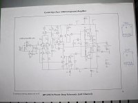
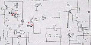
I'm afraid nothing very conclusive shows up there. The offset is OK and while the 1.14V between base and emitter of the Darlington sounds a little low (and it is possible the problem is here) it is in the right ballpark.
I have marked some expected voltages on the diagram. If these are OK then I think it would be worth swapping that upper NPN power Darlington transistor and seeing if the problem is fixed. The 0.6V marked is the voltage between base and emitter.
Attachments
We would normally recommend you to use a DBT (dim bulb tester) while working on something like this as it can save damage to parts if there are other problems.
It would also be a good idea to turn the bias preset (the 47 ohm) to give minimum bias before you power up with new transistors. Minimum bias is achieved when the preset is at minimum resistance i.e. when it is shorting pins 2 and 4 of the NPN and PNP outputs. If you look at the circuit it will become clear.
It would also be a good idea to turn the bias preset (the 47 ohm) to give minimum bias before you power up with new transistors. Minimum bias is achieved when the preset is at minimum resistance i.e. when it is shorting pins 2 and 4 of the NPN and PNP outputs. If you look at the circuit it will become clear.
- Status
- This old topic is closed. If you want to reopen this topic, contact a moderator using the "Report Post" button.
- Home
- Amplifiers
- Solid State
- Cambridge Audio Azur 540 A