Hello all, I was hoping to get some input on the possibilities of fixing the amplifier in this subwoofer that is not powering on. If I can get it repaired I will likely make a separate cabinet for the amp so it’s no longer abused by the woofer.
There is a small AC board that has the AC in, fuse, power switch, and transformer on it. On the photo of the backside of the board youll see two jumpers I’ve put in, this is to simulate the power switch being in the on position. This board sends the full 120vac to the main amplifier board to be rectified. The 120vac is also passed onto the small transformer that is on that board which then sends AC voltage to the small input board that has all of the controls for gain, frequency cutoff, the power led, phase, etc.
I measure the 120vac going into the transformer, but I’m only measuring mV coming out. Somewhere around 15-16 mVac. So it seems the small transformer is toast. On the output side of the transformer there is a bridge rectifier made up of four 1N4001s and filter capacitance of a pair of 220uf caps. I replaced them so they are 35v rated and I can’t find the old ones. It’s likely they were rated for less. So 1 amp of current and fairly low voltage.
Does anyone have any clue on how I can possibly get this repaired? Any schematic with voltages present? Anyone possibly with on they’re using as a parts unit that I could buy the transformer from???? Any help would be greatly appreciated.
Dan
Edit: well nevermind on the photos. For whatever reason it isn’t letting me upload them.
What are the power amplifiers? That might give a clue as to the power requirements.
Thank you for responding, the little transformer doesn’t actually go to the outputs, it’s meant strictly to power the input board. The outputs are IRFP350s
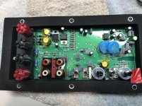
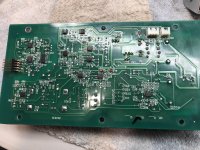
The input board doesn’t have all that much going on it, a couple of voltage regulators and then capacitors, diodes, resistors. There are several ICs (surface mount) on the back side.
Dan
Attachments
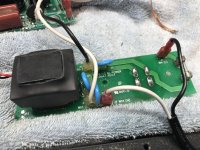
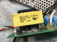
Here is one, I guess I can do one at a time. This is the AC board with the small transformer that isn’t outputting any voltage.
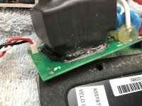
Before you give up on the transformer... take a close look at the solder work on that board. It's hard to tell from a photo but I see several solder points I would deem "highly suspect"....
Got you, ok. If the regs are 7815/7915 they need +-18vdc or so. A 15-0-15 transformer should be the ticket.
The trick is to understand what happens when you rectify AC to get DC.
When you read a transformer's secondary voltage with a multimeter they will give you the RMS voltage. (RMS is the "equivalent to DC when calculating work performed)
This is not the actual maximum voltage from the transformer... it is 1.41 times higher. So when you rectify and filter it... the actual DC output from the supply will be 1.4 times the rating on the transformer.
It's simple math ... 12vac X 1.41 == 16vdc.
It's simple math ... 12vac X 1.41 == 16vdc.
Indeed, I didn't show workings, just rule of thumbed it.
15vac rms x 1.41 = 21.15 peak
Less diode bridge 0.6v x 2 = 1.2v
21.15 - 1.2 = 18.95vdc
Allowing for wiring and transfomer losses under load, should come out around 18vdc
Got you, ok. If the regs are 7815/7915 they need +-18vdc or so. A 15-0-15 transformer should be the ticket.
Excellent, thank you so much! Any thoughts on softening the adhesive the used to glue it down? It’s rock hard and the pins were pushed through the glue so the thought of using dremel I had won’t work. I guess it’s not like I can damage the transformer any more than it already is. Just don’t want to damage the board.
Dan
Attachments
Last edited:
Before you give up on the transformer... take a close look at the solder work on that board. It's hard to tell from a photo but I see several solder points I would deem "highly suspect"....
I will certainly take a better look, but I was measuring directly at the input pins of the transformer measuring 120v and measuring directly at the output pins of the transformer when measuring no voltage.
I desoldered the output pins from the board and measured the pins directly desoldered from any circuit.
Dan
Last edited:
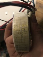
The thought came to me to cut through the heat shrink over the transformer, but the info doesn’t really provide much. I’ll just go for a generic 15v-0-15v.
Dan
Edit: so I got the transformer pulled from the board. I measured the resistance of the output coils. One coil is sitting at a perfect 19.0 ohms/189.7 mH and the other coil is measuring 16.2 ohms/189.5 mH.
Does this sound like its way off? If not, what else would cause me to get no voltage at the output?
Thank you
Edit again lol:
Just measured the input windings and both coils are open, duh.
Dan
Dan
Edit: so I got the transformer pulled from the board. I measured the resistance of the output coils. One coil is sitting at a perfect 19.0 ohms/189.7 mH and the other coil is measuring 16.2 ohms/189.5 mH.
Does this sound like its way off? If not, what else would cause me to get no voltage at the output?
Thank you
Edit again lol:
Just measured the input windings and both coils are open, duh.
Dan
Attachments
Last edited:
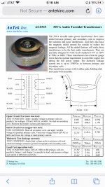
So I picked up a new transformer for the amp, and Antek AS-0515. I’m just looking for a hint on the wiring. My input is obvious, though there is a purple static shield wire I’m guessing I should just ignore. My question is on the output. It’s supposed to be a 15-0-15 transformer and has 4 wires coming out. Any others I’ve used had 3. There are two blue and two green. I’m guessing I’m supposed to wire two of the same color together to get the center tap?
So basically, how should I wire the output to get the 15-0-15?
Thank you,
Dan
So basically, how should I wire the output to get the 15-0-15?
Thank you,
Dan
Attachments
So I picked up a new transformer for the amp, and Antek AS-0515. I’m just looking for a hint on the wiring. My input is obvious, though there is a purple static shield wire I’m guessing I should just ignore. My question is on the output. It’s supposed to be a 15-0-15 transformer and has 4 wires coming out. Any others I’ve used had 3. There are two blue and two green. I’m guessing I’m supposed to wire two of the same color together to get the center tap?
So basically, how should I wire the output to get the 15-0-15?
Thank you,
Dan
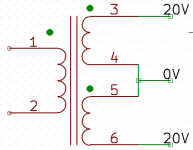
Do this - Take #3 is "Green" will be 15V, then #4 (Blue) and #5 (Green) and tie together for your "center tap" and then #6 is "Blue" then go to your rectifier to get ~20Vdc
Attachments
Do this - Take #3 is "Green" will be 15V, then #4 (Blue) and #5 (Green) and tie together for your "center tap" and then #6 is "Blue" then go to your rectifier to get ~20Vdc
Excellent thank you, so wiring it that was should get me about 15v ac on one green wire and on one blue wire?
Dan
Excellent thank you, so wiring it that was should get me about 15v ac on one green wire and on one blue wire?
Dan
No - it will configure your Dual-Secondary to a center-tapped (15-0-15 AC) toroidal.
~15VAC if you measure from either #3 or #6 (red probe) and the combined #4/5 (center-tap) (black probe) and will be slightly higher with no load.
Alternately you will get 30VAC measured at #3 and #6 only.
No - it will configure your Dual-Secondary to a center-tapped (15-0-15 AC) toroidal.
~15VAC if you measure from either #3 or #6 (red probe) and the combined #4/5 (center-tap) (black probe) and will be slightly higher with no load.
Alternately you will get 30VAC measured at #3 and #6 only.
Excellent, that’s what I meant.
Thank you,
Dan
Great work!Thanks all, installed the transformer and it’s working perfectly.
Dan
- Status
- This old topic is closed. If you want to reopen this topic, contact a moderator using the "Report Post" button.
- Home
- Amplifiers
- Solid State
- No power from Velodyne SPL10BGII