I am working on many basic amps
And most manuals don't say which connector is + and which one is -
So you sort of have to guess and search online
Is there a standard convention like positive terminal is mentioned first, negative second
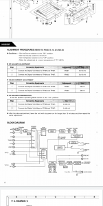
Here is a snapshot of harman 6650r bias adjustment procedure
Which one of them needs to be connected to positive multimeter terminal and which one to negative
Tp407 is definitely negative I think. Black colored cable. 406 and 405 are white and red
And most manuals don't say which connector is + and which one is -
So you sort of have to guess and search online
Is there a standard convention like positive terminal is mentioned first, negative second
Here is a snapshot of harman 6650r bias adjustment procedure
Which one of them needs to be connected to positive multimeter terminal and which one to negative
Tp407 is definitely negative I think. Black colored cable. 406 and 405 are white and red
Attachments
The meter polarity doesn't matter for either offset adjustment, or for bias adjustment.
For offset, just connect the meter leads either way and trim to zero.
For output bias, just connect the meter leads either way and trim to the specified magnitude,
ignoring the sign.
For offset, just connect the meter leads either way and trim to zero.
For output bias, just connect the meter leads either way and trim to the specified magnitude,
ignoring the sign.
Last edited:
But sometimes adjustments allow for from -10mv to +10mv adjustment
On some nakamichi idle needs to be around 24mv.
And variable resistors can adjust from -20 to +30mv
Sure, if the specified range is asymmetric, then you need to observe the correct polarity.
The polarity should then be marked on the pcb, by + for example. But the output bias current
can only be in one direction, so just the magnitude is of interest.
Last edited:
- Status
- This old topic is closed. If you want to reopen this topic, contact a moderator using the "Report Post" button.