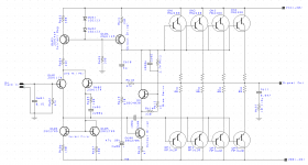
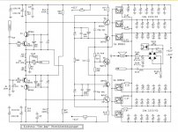
I stripped a whole bunch of old Sony amps and I would like to re-purpose the output transistors. I looked at the schematic for one and it was a class h amplifier using a 2 pairs of MN2488 and MP1620 Darlington Transistors. I have attached the schematic I came up with from it. I am new to building (Kind of anyway) I usually just modify existing amps to put out more power.
Can anyone that has built a few look this over and tell me if there is anything I have totally messed up or can do to improve it before I get the boards made?
Also
I would really like to see a schematic of a class ab amplifier and have someone explain to me what every part does or point me to a book that goes into more detail that just This is a long tail pair, This is a driver stage, ETC ETC ETC.
I am really hoping a guru can help me here. I have been in the electronics industry for 30+ Years so don't worry about getting to technical.
Attachments
A few things at first blush ...
1) You probably should make your bias circuit at Q9 adjustable.
2) Bypass your feedback resistor at R618 with a small value cap to prevent high frequency oscillations.
3) You might consider a thiel network on the output... half a dozen turns of wire around a resistor in series and a small value cap to ground.
4) Some RF bypassing on the gain stages might also be a good idea.
5) with 40 volt rails you really don't need 4 pairs of 10 amp transistors... 2 pairs would probably suffice and may even work better. More output transistors does not give you more power.
Just one question .... how the heck did you manage 30 years in electronics without learning how an amplifier works?
You might want to visit this thread and get the book ...
Last edited:
Blowing off the dust. I repaired audio equipment for about 15 years of that, over 15 years ago. I honestly have not touched it in years and now the kids are grown and I have more time to play with the things I wanted to in my younger years. But there is so much I do not remember about it. It is actually driving me nuts.
I spent the last 15 dealing with digital circuits and machine controls. Router, Switches, Sensors, Micro controllers and stuff like that. A lot of programming and design of test equipment. Guess what! All of the transistors are built into the chips. The last time I calculated the gain on a transistor was in the dark ages. I can't remember the last time I calculated anything in that was not in Hexadecimal. Add to that I spent the last 3 years doing mostly mechanical and electrical (Not electronic) interface design on test equipment.
I can honestly say from experience if you don't use it you do lose it.
Some of it is still there.
1) Easy enough
2) Refresher I am creating a filter RC Filter Low pass filter on the feedback loop to stop the amp from going into parasitic oscillation. I am thinking shoot for about 30Khz or about 1500pf.
3) Got it.
4) This one escapes me. I will have to some homework. Just to make sure I do it right. Caps??? But how to implement them.
Blowing off the dust. I repaired audio equipment for about 15 years of that, over 15 years ago. I honestly have not touched it in years and now the kids are grown and I have more time to play with the things I wanted to in my younger years. But there is so much I do not remember about it. It is actually driving me nuts.
Sounds like my story ... grown kids, divorced, retired and lots of time on my hands ... If only there was lots of money.
")
I spent the last 15 dealing with digital circuits and machine controls.
Me too ... computers, light mechanical and office automation.
I can honestly say from experience if you don't use it you do lose it.
Some of it is still there.
I was in the same spot about 5 years ago. Needed a refresher and some reminding... that's where the link in my signature comes from.
1) Easy enough
Good.
2) Refresher I am creating a filter RC Filter Low pass filter on the feedback loop to stop the amp from going into parasitic oscillation. I am thinking shoot for about 30Khz or about 1500pf.
It can be a simple capacitor or a capacitor and a resistor in series. The values will depend on whether the amplifier's gain crosses the point where phase shift creates positive feedback to cause oscillations. With most modern semiconductors that could be as high as 200khz... if at all. But bringing the gain below unity around 100khz seems like a good place to start.
You may find This Video helpful.
This is why we build on protoboard before we order circuit boards. There's always a mess of tinkering to be done before we trust the design.
3) Got it.
Easy enough to do, been around forever.
4) This one escapes me. I will have to some homework. Just to make sure I do it right. Caps??? But how to implement them.
What happens is if a strong RF field, say from a nearby transmitter, gets into the base emitter junction of a transistor it acts like the detector diode in an AM radio and while the RF is gone, the modulation (not always audio) remains. In the Amateur Radio world it's called "Audio Rectification" and researching it is a very interesting read.
To prevent this kind of interference you need to shunt RF off of the more sensitive inputs in a circuit. Generally a few picofarads across the base emitter junction or a ferrite bead in series with the base is enough to prevent it. As a matter of course I always add ferrite beads on all my inputs right at the connectors.
Now to be fair, you may not have this problem because the guts of an amplifier tend to be very low impedance... but the provision for it should be there none the less. With most transmitters using FM these days, the odds are it could happen, you won't even hear it, except as periodic bursts of unexplained distortion.
So there you go...
I'm sure the others will chime in with more, maybe better, suggestions as well.
Last edited:
Did anyone mention the input filter and AC coupling the input? It is not suitable as drawn.
The feedback return is to the neg rail rather than ground which will introduce ripple into the signal path. The 10v cap won't last long
Typo for 330 ohm for R608?
A bit of inductance at the output probably wouldn't go amiss.
The feedback return is to the neg rail rather than ground which will introduce ripple into the signal path. The 10v cap won't last long
Typo for 330 ohm for R608?
A bit of inductance at the output probably wouldn't go amiss.
Most transmissions these days are QAM16/QAM256 or suchlike, spread-sprectrum or TDMA, ie _digital_, and most of this is amplitude and frequency/phase modulated. The commonest breakthrough heard is mobile phone packet bursts.With most transmitters using FM these days, the odds are it could happen, you won't even hear it, except as periodic bursts of unexplained distortion.
Most transmissions these days are QAM16/QAM256 or suchlike, spread-sprectrum or TDMA, ie _digital_, and most of this is amplitude and frequency/phase modulated. The commonest breakthrough heard is mobile phone packet bursts.
... or the CBer living next door... "Breaka Breaka Any Takah"...
Last edited:
That brings back memories. Back in the early 90's a friend of mine would talk over his TV to mess with his wife. He had a 1000w linear. We used to talk to Ham operators in China with it from Idaho. Especially when the atmosphere was just right and he could get some good skip going. He did that until the day he got busted by the FCC. I guess the neighbor was tired of getting his signal stomped and complained.
That brings back memories. Back in the early 90's a friend of mine would talk over his TV to mess with his wife. He had a 1000w linear. We used to talk to Ham operators in China with it from Idaho. Especially when the atmosphere was just right and he could get some good skip going. He did that until the day he got busted by the FCC. I guess the neighbor was tired of getting his signal stomped and complained.
Thing is, the only reason that has mostly stopped is not because audio companies got on their game and started bypassing their electronics... it's because the CB fad died and Amateur Radio is right behind it.
As Mark points out, these days it's mostly cellphones and routers causing the problems and, fortunately, they're a lot easier to filter.
The input pair is drawn as emitter followers, which is probably not right.
The transistor was tied to the NPN Symbol in my library. It is fixed now.
The transistor was tied to the NPN Symbol in my library. It is fixed now.
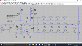
An updated schematic would be good, right about now....
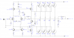
Updated Schematic.
Thanks ... It's really coming along...
Couple of thoughts...
Your feedback path through R10 is leading to the base of Q2, without some voltage division there, it's likely your amp will have very low gain. If you eliminate c620 and connect r9 to the base of Q2 you will get some real gain out of it... too much in fact. You may want to consider adjusting R10 down to about 12k or 15k and recalculating the gain and the value of C19.
I've seen it both ways but IIRC your Theil network on the output would be more effective if C11 and R17 were after R18, right on the output.
If C604 is there for RF avoidance it might be better connected base to emitter of q8, it might also be a good idea to do the same with Q6.
For further RF avoidance, I would suggest a small value cap right on the input pins, before the coupling capacitor, also.
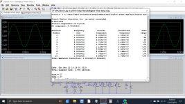
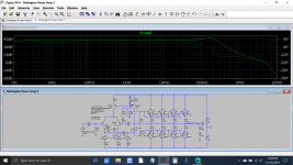
Here is a quick sim of the design with some of the points mentioned corrected. Bias is set to 100ma per pair.
Can I get the LTSpice models for the power transistors from you, please?
- Status
- This old topic is closed. If you want to reopen this topic, contact a moderator using the "Report Post" button.
- Home
- Amplifiers
- Solid State
- I have about 30 Darlington Pairs