Hi,
Have Cyrus Two with PSX, working excellent since 1992 until I managed to shortcut one of the loudspeaker cables (don't ask me how...).
Now it is dead, well both the Cyrus Two and the PSX light up when you turn them on, but no sound at all. I suppose that means the fuses are OK?
There was a light smell so probably some components got damaged. When this occured I haven't started to play so there was no output to the speakers, it occured as soon as I switched power on.
So is just teh amplifier damaged, or also the PSX?
Grateful for all advices.
Regards Robert
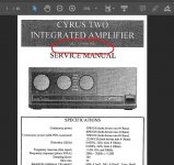
The service manual is available here: Two Fault Finding - Issue 07 And Tog - Cyrus Two Service Manual [Page 51]
There are lots of internal fuses which you can check for starters.
There are lots of internal fuses which you can check for starters.
This was for a Cyrus 1 but the power amp looks pretty similar. It will give you an idea of what is involved.
cyrus 1 output transistor question. push-pull?
cyrus 1 output transistor question. push-pull?
Hi again Robert!
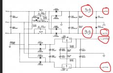
The fact that you shorted out only one of the loudspeakers, but both channels have stopped working, just may indicate the fuses have blown in the power supply. Check F1 and F2 which are shown in the power supply schematic.
If the problem extends to the power amp, then the output transistors may have been protected by the fusible resistors R89 to R95 (indicated by exclamation marks in the power amp schematic).
If you don't have experience of trouble shooting at component level, I suggest you contact Cyrus Servicing. Servicing – Cyrus Audio
Such servicing work does not come cheap though!
Although, to their credit, Cyrus offer a fixed rate of £300 for servicing the Cyrus 2.
We offer fixed fee servicing to ensure that the consumer is fully aware of the exact cost of the work upfront, avoiding any unpleasant surprises even in the case of extensive remedial work.The quoted price is inclusive of all parts, labour, and VAT, and includes a six-month warranty.
Last edited:
Hi all
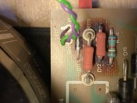
I'm posting this as a long shot that someone might be able to help, although I realise it's an old thread. I recently inherited a Cyrus Two amp from my late father-in-law which has blown, and I'm going to try repairing it myself. Having looked at the PCB it looks as if the issue is around the power area, with D11, D12, R119 and R114 all featuring scorch marks. Having had a brief contact with Cyrus I have been told the resistors and diodes required for D11 and R114, and have worked out that R119 is a 100R resistor. However I am at a loss to which part I need for D12. Cyrus have gone quiet on me and the parts list does not mention D12. Bizarre. I found this thread while searching Google and you all seem to have a lot more knowledge than me, so I hope you can help.
I'm posting this as a long shot that someone might be able to help, although I realise it's an old thread. I recently inherited a Cyrus Two amp from my late father-in-law which has blown, and I'm going to try repairing it myself. Having looked at the PCB it looks as if the issue is around the power area, with D11, D12, R119 and R114 all featuring scorch marks. Having had a brief contact with Cyrus I have been told the resistors and diodes required for D11 and R114, and have worked out that R119 is a 100R resistor. However I am at a loss to which part I need for D12. Cyrus have gone quiet on me and the parts list does not mention D12. Bizarre. I found this thread while searching Google and you all seem to have a lot more knowledge than me, so I hope you can help.
An externally hosted image should be here but it was not working when we last tested it.
That's it 
So... from left to right we have a diode and three resistors. That oxide red part where it says D12 is a resistor.
Also looking on a Cyrus 2 circuit and I can't just locate an R119... but there are two R115's
The diode/s I would suggest you would be safe with 1N4004 or 1N4007.
Your picture doesn't look anything like the circuit diagram though.
Attachments
I'll have to leave it for today but your picture seems to show the LED wiring and so that all looks to be elsewhere on the circuit diagram and with other component references.
The circuit I'm looking at is for a Cyrus 2 but obviously something isn't right with the versions and that means it is no use trying to advise you based on that as it will be incorrect and confusing.
If!!! those parts are related to just the LED then I doubt they will be the cause of the fault tbh as that would not stop the amp working.
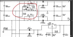
Edit... found a different version of the power supply with R119.
So it is just for the LED. If the amp is otherwise dead then these alone won't be the cause.
One for tomorrow")
The circuit I'm looking at is for a Cyrus 2 but obviously something isn't right with the versions and that means it is no use trying to advise you based on that as it will be incorrect and confusing.
If!!! those parts are related to just the LED then I doubt they will be the cause of the fault tbh as that would not stop the amp working.
Edit... found a different version of the power supply with R119.
So it is just for the LED. If the amp is otherwise dead then these alone won't be the cause.
One for tomorrow
Attachments
I'm pleased you said that, because I couldn't make head nor tail of the circuit diagram either, even though I don't really know what I am looking at. One thing that has confused me is that if you go buy the Cyrus 2 PCB parts list, anything with a D should indicate a diode, so why would a resistor be where a diode should be in D12? I do know my father-in-law would have been unlikely to have attempted any repairs to this himself, but I wonder if anyone else has?
I suspect there may be errors possibly both with the board markings and the component references in the manual.
Could D12 actually mean R120?
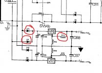
If you look at the circuit it shows two 100 ohm resistors effectively in series together with a IN4002. Those are placed across one side of the transformer winding.
The LED is across the 1N4004.
Electrically it is OK but the values are just crazy because 200 ohm in total will pull a lot of current. If the AC is say 30 volts (which is mentioned in the manual) then the peak current is (30*1.414) / 200 which is 200 milliamps. That can't be right. Ancient old inefficient LED's use a twentieth of that.
I think it's going to be best not to assume anything but begin by looking at the fault presented and working from that point.
Could D12 actually mean R120?
If you look at the circuit it shows two 100 ohm resistors effectively in series together with a IN4002. Those are placed across one side of the transformer winding.
The LED is across the 1N4004.
Electrically it is OK but the values are just crazy because 200 ohm in total will pull a lot of current. If the AC is say 30 volts (which is mentioned in the manual) then the peak current is (30*1.414) / 200 which is 200 milliamps. That can't be right. Ancient old inefficient LED's use a twentieth of that.
I think it's going to be best not to assume anything but begin by looking at the fault presented and working from that point.
I was under the impression that the parts in question that need replacing relate to the power supply (P17 of the manual), which is why the unit doesn't power up. This is a series 7 amp and the paragraph in the manual relates to series 6, however.
Do you think it's worth replacing like for like here? Is that what you mean by looking at the fault presented?
I'm no expert in these matters. I think I can replace a couple of parts but finding other faults could well be beyond me!
Do you think it's worth replacing like for like here? Is that what you mean by looking at the fault presented?
I'm no expert in these matters. I think I can replace a couple of parts but finding other faults could well be beyond me!
We do really need a correct diagram in order to be able to match what you are seeing. This the manual I'm which supposedly covers all versions.
That area of the circuit does seem to be just related to the LED... maybe it is a bulb rather than LED which would explain the crazy values...
Start at the beginning which is always to check all voltage supplies are correct. There are two fuses shown and four points to check voltages on. +vreg and -vreg should have approx + and - 18 volts respectively on each point. There should be approx 40 volts DC on each fuse and at each end of the fuse.
Those are your first tests. Just to replace parts in hope isn't really a good plan.
Attachments

Yes Mooly you suspect well there are errors with the board and the manual.I suspect there may be errors possibly both with the board markings and the component references in the manual.
Could D12 actually mean R120?
If you look at the circuit it shows two 100 ohm resistors effectively in series together with a IN4002. Those are placed across one side of the transformer winding.
The LED is across the 1N4004.
Electrically it is OK but the values are just crazy because 200 ohm in total will pull a lot of current. If the AC is say 30 volts (which is mentioned in the manual) then the peak current is (30*1.414) / 200 which is 200 milliamps. That can't be right. Ancient old inefficient LED's use a twentieth of that.
I think it's going to be best not to assume anything but begin by looking at the fault presented and working from that point.
D12 is R120, i replaced the 2X100R (R119 and R120) with 3W resistors because the others was very hot(smoke), but they still remains very hot.
I am very surprise of this, i am asking myself " why not taking the power after the bridge and use one 3.9k 1Watt resistor"
I am looking for the PLED H514B-5 datasheet..Thanks
R119 and R120 are shown as feeding just the LED from the AC side of the bridge. 100 ohm looks very wrong. I would fully expect those values to smoke tbh Quick guess would be something more like 10k as being suitable. The PLED H514B-5 is just an LED.
If fed from after the bridge it would fade out slowly on power off rather than an abrupt off. On advantage is the LED flicker would be removed.
Quick guess would be something more like 10k as being suitable. The PLED H514B-5 is just an LED.If fed from after the bridge it would fade out slowly on power off rather than an abrupt off. On advantage is the LED flicker would be removed.
- Home
- Amplifiers
- Solid State
- Advice needed - blown Cyrus Two