THAT IC Selection Guide
XLR pin 1 should be connected to the metalwork of the amplifier housing.
If your amplifiers have single ended (unbalanced) inputs you need a difference/differential amplifier rather than the two non inverting buffer? amplifiers shown.
The most expeditious way to realise a balanced input would be to use a balanced line receiver such as in the link above. The THAT 1206 has a differential to single ended loss of 6dB and would be my choice.
Keith
That's not the way to do it - if the ground is not where you think the amp's may both clip at low signal levels - and only be using one output transistor due to asymmetry. The reason to use differential signalling in the first place is because source and destination grounds can be different.
Some sources only drive one wire of the pair.
So feed the inputs to a differential to single ended converter stage, then invert this to drive a bridged load. The system should be unaware of the common mode voltage of the inputs (within reason). Typical systems can handle +/-25V of common mode on a 2V signal, due to the differential->single ended converter. Your scheme can't handle common-mode gracefully unless its very small.
Indeed.Your scheme can't handle common-mode gracefully unless its very small.
Mind you, if you insist on a fully balanced power amp, you can always use a cross-coupled pair of balanced receivers to drive it. Takes a bit more effort in the input section, of course.
I see no reason for an extra Diff to SE converter and back to Diff.
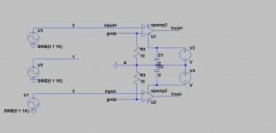
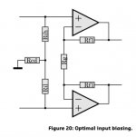
The error in the shown circuit diagram is that there are no feedback resistors and that the two resistors connected to the minus input are grounded in the middle.
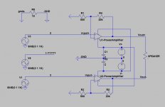
With the corrected diagram below, Common mode rejection is excellent, and since the speaker is floating, no sound will be produced when offering a common mode signal.
On both sides the protocol tells that pin 1 has to be connected to the casing, that preferably has to be connected to mains gnd on both side.
Somewhere inside, the Signal Gnd has to be connected to the Casing also.
Even in case of an SE preamp out, signal can be easily made balanced by inserting a resistor in the cold line of equal value as the hot line.
Hans

The error in the shown circuit diagram is that there are no feedback resistors and that the two resistors connected to the minus input are grounded in the middle.
With the corrected diagram below, Common mode rejection is excellent, and since the speaker is floating, no sound will be produced when offering a common mode signal.
On both sides the protocol tells that pin 1 has to be connected to the casing, that preferably has to be connected to mains gnd on both side.
Somewhere inside, the Signal Gnd has to be connected to the Casing also.
Even in case of an SE preamp out, signal can be easily made balanced by inserting a resistor in the cold line of equal value as the hot line.
Hans
A
NOT chassis gnd, and not amp refs cus connecting both amp refs togethers creating loop.
Could you translate that in somewhat understandable English.
I’ve no idea what you are trying to mention.
Hans
I see no reason for an extra Diff to SE converter and back to Diff.
The error in the shown circuit diagram is that there are no feedback resistors and that the two resistors connected to the minus input are grounded in the middle.
With the corrected diagram below, Common mode rejection is excellent, and since the speaker is floating, no sound will be produced when offering a common mode signal.
I suppose my question would be whether you want to do common mode rejection on the speaker outputs. Seems to me that a good sized spike of noise could easily clip both amplifiers causing all sorts of havoc. It actually makes sense to invert and add the XLR signals in the conventional manner then invert again to drive BTL loads, just to avoid this.
The conversions are not all that difficult...
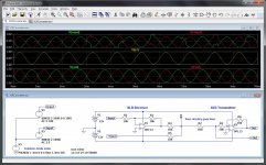
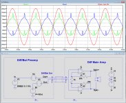
If you look at the thumbnail below you will see the advantage ... the inputs on the top traces are showing a lot of common mode noise but once through the summing resistors it's completely gone from the middle panel. The bottom panel shows a nice clean differential output that could be fed to your power amps.
Attachments
Last edited:
I regret that the first scheme was drawn wrong. This last scheme is closest to the real one. Practically speaking, there are two ordinary single ended power amplifiers on each channel.
O.k. tie the two 500R resistors together, isolated from gnd and you have a real fully differential main amp.
I still have a bit of a problem with the three sources V1, V3 and V5.
What exactly do they represent, three independant sources and why is V5 connected to pin 1 ?
As mentioned already, a SE source can be converted in a balanced source with a simple resistor.
Hans
I disagree, there is no need for this additional complication.I suppose my question would be whether you want to do common mode rejection on the speaker outputs. Seems to me that a good sized spike of noise could easily clip both amplifiers causing all sorts of havoc. It actually makes sense to invert and add the XLR signals in the conventional manner then invert again to drive BTL loads, just to avoid this.
The conversions are not all that difficult...
If you look at the thumbnail below you will see the advantage ... the inputs on the top traces are showing a lot of common mode noise but once through the summing resistors it's completely gone from the middle panel. The bottom panel shows a nice clean differential output that could be fed to your power amps.
The circuit diagram as shown has a perfect CMRR, see image below.
V(out+) and V(Out-) are common mode polluted to the main amp's input.
At the speaker output, in this image divided by 40 to get the same scale, this common mode signal is completely removed.
Hans
Attachments
It's ok that ?
Yes, that is O.K. when Rcd is large enough, preferably >100K.
That will keep the outputs at zero volt when no source is connected.
This resistor will be the Common Mode input resistance of your amp, while the Differential input resistance will be 1K.
Hans
I disagree, there is no need for this additional complication.
The circuit diagram as shown has a perfect CMRR, see image below.
V(out+) and V(Out-) are common mode polluted to the main amp's input.
At the speaker output, in this image divided by 40 to get the same scale, this common mode signal is completely removed.
Hans
No, sorry. The circuit you give has unity common mode gain. So it certainly doesn't remove common mode at all. If the inputs have a large common-mode offset the power amplifiers will be clipping asymmetrically, and the cross-over points will be shifted.
Or put another way the ouput is unbalanced if there's a common mode offset, and will intermodulate the common mode signal with differential signal if the power amps have any cross-over distortion.
The standard instrumentation amp circuit uses that front end to get differential gain, then a differential opamp stage to remove the common mode signal. The differential gain comes from the input stage, the common mode attenuation from the second. The combination has very high CMRR at the single-ended ouput.
The point of doing diff->SE conversion is to map to the new ground potential, then you invert to generate a _balanced_ pair of signals to drive the bridged power amps.
All these BAL>SE>BAL conversions have such a strong sonic imprint it is almost comical to consider using them just to placate some engineering goddesses")
Utter falsehood.
- Status
- This old topic is closed. If you want to reopen this topic, contact a moderator using the "Report Post" button.
- Home
- Amplifiers
- Solid State
- Fully balanced amplifier input wiring