I'm sorry Mark, but you are wrong.No, sorry. The circuit you give has unity common mode gain. So it certainly doesn't remove common mode at all. If the inputs have a large common-mode offset the power amplifiers will be clipping asymmetrically, and the cross-over points will be shifted.
Or put another way the ouput is unbalanced if there's a common mode offset, and will intermodulate the common mode signal with differential signal if the power amps have any cross-over distortion.
The standard instrumentation amp circuit uses that front end to get differential gain, then a differential opamp stage to remove the common mode signal. The differential gain comes from the input stage, the common mode attenuation from the second. The combination has very high CMRR at the single-ended ouput.
The point of doing diff->SE conversion is to map to the new ground potential, then you invert to generate a _balanced_ pair of signals to drive the bridged power amps.
It is correct that common mode gain is one, but on both sides of the speaker, the end result is no signal to the speaker.
Put things in LTSpice and you will notice what wrong in your opinion.
Hans
I disagree, there is no need for this additional complication.
The circuit diagram as shown has a perfect CMRR, see image below.
V(out+) and V(Out-) are common mode polluted to the main amp's input.
At the speaker output, in this image divided by 40 to get the same scale, this common mode signal is completely removed.
Take a look at each power amp's output individually... the noise will still be there and greatly amplified. That it does not appear on the summed BTL signal to the speaker does not stop it from clipping the individual amplifiers or causing other kinds of distortion. My method cleans all that up right at the input.
Plus, if you have anything between the XLR input and the amplifier, such as a volume control, tone controls or additional gain, converting to single ended halves the parts count and saves those elements from having to deal with the distortion as well.
Last edited:
No, the noise in a diff topology will be increased by 3dB compared to a single amp.Take a look at each power amp's output individually... the noise will still be there and greatly amplified. That it does not appear on the summed BTL signal to the speaker does not stop it from clipping the individual amplifiers or causing other kinds of distortion. My method cleans all that up right at the input.
Plus, if you have anything between the XLR input and the amplifier, such as a volume control, tone controls or additional gain, converting to single ended halves the parts count and saves those elements from having to deal with the distortion as well.
There is no clipping at all since CM is amplified a factor 1 versus 40 for a diff input signal, way better than a SE amp.
The question from the OP was diff to diff.
Lets stick to that.
Hans
Indeed, but that's not what I'm talking about, there is a common-mode signal injected into both amps, shifting the cross-over point and the clipping threshold.I'm sorry Mark, but you are wrong.
It is correct that common mode gain is one, but on both sides of the speaker, the end result is no signal to the speaker.
I am not saying the differential signal seen by the speaker is affected directly, but that the system is not balanced, and will be indirectly impacted by the shifts.Put things in LTSpice and you will notice what wrong in your opinion
Hans
A standard diff->SE conversion will handle > +/-25V of common mode (assuming standard opamp rails and circuit) without any shifting of clipping or cross-over point and is standard practice for this reason (and because not all setups are bridged of course). Basically no common-mode signal gets into the system past the input differential amp.
Your approach pushes the common mode signal right through the amp and out the other side. From the point of view of the speaker signal the common mode input is directly injected onto both power rails. Its not balanced unless the input is balanced and originating from a system with the same ground potential. If the systems were at the same ground potential there would be little need for a differential signal in the first place.
Run your simulation with 25V mains hum as common-mode on the inputs and look at the behaviour.
[ edit: Actually thinking about this a bit more I think this approach might wreak havoc with conventional speaker protection circuits ]
Last edited:
The question is, how often do you see this much common-mode signal in practice? I would imagine that it takes a pretty pathological case. Unbalanced preamp connected to a modern TV or similar that isn't grounded, with no extra ground connection between pre and power amp involved? Laptop with 2-prong AC adapter plugged into portable mixer going into power amp (again, just unbalanced out to bal in+/in- and nothing else)?
One might argue that yes, it can happen, but is comparatively easy to avoid with proper cabling. That leaves just the common-mode component of an unbalanced signal... which might still contribute a bit of odd-order distortion.
That said, the extra balanced receiver enables adding an input level trim (volume control), for minimizing the noise penalty of a balanced connection and optimizing overall gain structure (with sensitive speakers, you may not want very much power amp gain at all). Which is precisely why commercial PA/studio amplifiers usually have one.
Last edited:
Normally you want the true single-ended signal for some processing anyway, be it tone/EQ, vu-meter, headphone jack. So its rare you can leave things differential all the way through an analog amp. A bridged-only amp is a pretty special case.
The words "Fully balanced" occur in the subject line, I guess the question is whether this means "roughly balanced depending" or not (!)
The words "Fully balanced" occur in the subject line, I guess the question is whether this means "roughly balanced depending" or not (!)
No, the noise in a diff topology will be increased by 3dB compared to a single amp.
There is no clipping at all since CM is amplified a factor 1 versus 40 for a diff input signal, way better than a SE amp.
The question from the OP was diff to diff.
Lets stick to that.
Read what I wrote...
Running the out of phase "balanced" signals directly into a BTL amp is in fact passing the common mode noise directly into each amplifier. No cancellation occurs until it hits the speakers.
My way eliminates the interference at the input, before it is amplified and before it threatens to clip one of the two amps in the BTL configuration.
It's not rocket science... feed in a test signal on on phase of the balanced input and you will read it directly on the output of the corresponding amplifier... now do the other phase... there is no common mode rejection in that system whatsoever.
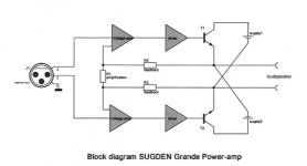
Sugden Grande monoblock amplifier A class.
That tells the whole story.
Hans
Read what I wrote...
Running the out of phase "balanced" signals directly into a BTL amp is in fact passing the common mode noise directly into each amplifier. No cancellation occurs until it hits the speakers.
My way eliminates the interference at the input, before it is amplified and before it threatens to clip one of the two amps in the BTL configuration.
It's not rocket science... feed in a test signal on on phase of the balanced input and you will read it directly on the output of the corresponding amplifier... now do the other phase... there is no common mode rejection in that system whatsoever.
Wrong again.
The common mode signal is not passed directly to the speakers, but attenuated already by a factor 40 or 32dB. But on top of that you get the suppression at the LS output between the 2 channels that will add at least another 20dB to 40dB resulting in 60 to 80dB in total.
As mentioned, with this attenuation, a CM signal can never lead to clipping even up to close of the supply level, let’s say 25Volt.
But such a ridiculous CM signal will never occur.
Compare this to your circuit, what is the CMRR, maybe 40 dB or at the most 50dB with 0.1% resistors.
And what is the maximum CM input signal, is it better ?
On top of that you get the extra noise of this circuit that is far from low.
So all in all I see no single benefit in your solution.
Hans
Sugden Grande monoblock amplifier A class.
Sugden Grande Mono Block Power Amplifiers (Pair)
Note: "Each mono block houses dual matched amplifiers with the output stages in the floating bridged mode."
If you are doing this for power, fine, if quality, can you match the amplifiers sufficiently?
As has been noted a couple of times already on this thread, balanced and differential are two different things but often get lumped together on the assumption that differential inputs are balanced.. So its rare you can leave things differential all the way through an analog amp.
Last edited:
Wrong again.
The common mode signal is not passed directly to the speakers, but attenuated already by a factor 40 or 32dB. But on top of that you get the suppression at the LS output between the 2 channels that will add at least another 20dB to 40dB resulting in 60 to 80dB in total.
As mentioned, with this attenuation, a CM signal can never lead to clipping even up to close of the supply level, let’s say 25Volt.
But such a ridiculous CM signal will never occur.
Compare this to your circuit, what is the CMRR, maybe 40 dB or at the most 50dB with 0.1% resistors.
And what is the maximum CM input signal, is it better ?
On top of that you get the extra noise of this circuit that is far from low.
So all in all I see no single benefit in your solution.
Hans
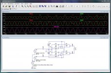
Okay ... take a look at the thumbnail... Here we have a pair of amplifiers in a BTL configuration being fed by a balanced (i.e. out of phase) input pair. As you suggested I am feeding the input signals directly into the amplifiers.
The top two traces are the inputs which start out clean and then suffer some common mode noise.
The middle two traces are the amplifier's outputs... I see the noise, I see clipping, I see distortion. Since the amplifiers are clipping, the common mode noise is not filtered at the output... and it will become audible along with the clipping.
Finally the bottom trace is the BTL output... not so good is it?
Attachments
Last edited:
^How on earth could a balanced source produce a 1V common mode signal, IF the source reference (ground, or whatever you may call it) is connected with the amp with a low impedance link? 1V over 1 Ohm produces 1 A of equalizing currents....
In your example, you are using ground as a rock solid reference, but if a real world source references to the same ground it would not be possible to produce such an extreme CM signal.
In your example, you are using ground as a rock solid reference, but if a real world source references to the same ground it would not be possible to produce such an extreme CM signal.
^How on earth could a balanced source produce a 1V common mode signal, IF the source reference (ground, or whatever you may call it) is connected with the amp with a low impedance link? 1V over 1 Ohm produces 1 A of equalizing currents....
In your example, you are using ground as a rock solid reference, but if a real world source references to the same ground it would not be possible to produce such an extreme CM signal.
It's rare, but I've seen XLR cables with 10 and 20 volt spikes riding on them from being passed near high voltage tubes, motors, transmitters and other noise sources.
It's pretty easy to ignore outside interference, but that is exactly what the XLR cables were developed to deal with.
Last edited:
Ok. I appreciate that you tried to come with some prove.Okay ... take a look at the thumbnail... Here we have a pair of amplifiers in a BTL configuration being fed by a balanced (i.e. out of phase) input pair. As you suggested I am feeding the input signals directly into the amplifiers.
The top two traces are the inputs which start out clean and then suffer some common mode noise.
The middle two traces are the amplifier's outputs... I see the noise, I see clipping, I see distortion. Since the amplifiers are clipping, the common mode noise is not filtered at the output... and it will become audible along with the clipping.
Finally the bottom trace is the BTL output... not so good is it?
Unfortunately you have connected the junction of R3 and R4 to gnd.
Take it away, and the result is below, output is clean as it can be.
I have left the power supply because it takes no part in the equation.
Hans

Yes indeed, I was right now thinking that the result was impossibly bad.
Instrumentation amplifier - Wikipedia
The neg inputs must be left floating toward ground.
There is really no need to add more than just to wire up the signal inputs and feedback paths around the amp correctly.
- Status
- This old topic is closed. If you want to reopen this topic, contact a moderator using the "Report Post" button.
- Home
- Amplifiers
- Solid State
- Fully balanced amplifier input wiring