Of course this version needs a fresh new PCB
I believe I was able to design a new schematic so that the modifications to the original Goldmund schematic/pcb are minimal...anything added can hang in the air or placed on a small test pcb. Eg. the complete arrangement around the Vbe multiplier replaces one resistance (R7 in your first post), so you need to set/solder everything up on a small pcb and fix it to the main heatsink along with the output M-fets via the screw and tab on the bias transistor (Q15 on my last schematic) and wire with 2 wires where R7 use to be...done! Note that all small transistors can be placed on top of the pcb without any heatsink, DC offset trimer U1 can be solder to Q10/Q11 collectors and resistors R11/R30 via solid wire etc...be creative it's all about diy.
")
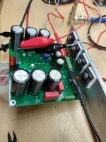
After the fireworks obtained from the copied board I was working on, and as I told you before, I discovered a single fatal error. I placed a 33 Ohms R2 instead of a 330 Ohms and everything went wrong. A couple of days ago, I started to build a fresh new PCB, complete with Exicon MOSFETs. I am talking of the original schematic, not any of the mods we have been talking over the last days. In this original schematic version I replaced almost all the transistors by Zetex ZTX658 and ZTX758, except for the 4 x BC546 at the front end, up and down the dual JFET 2N5565.
The good news:
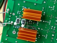
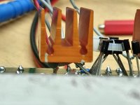
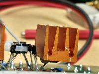
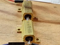
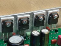
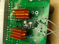
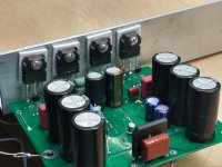
Transistors were placed on the bottom side of the PCB and heat sinks fixed with epoxy on. Q9 and Q12 in thermal contact same as Q10 and Q11. You may try to see this on the pictures. Oscilloscope on output, no speaker connected, Variac for mains, voltmeter across 0.1 Ohms quiescent current monitor, the amplifier turned on, no heating, no oscillation, almost 0mV DC at the output. With input grounded, 0mA quiescent current on output MOSFETs. After this, signal generator, still no speakers, and a light load, obtained 110 Vpp clean sine @ 1kHz before clipping.
The bad news:
Small speakers 8 Ohms connected at the output, small signal input. Unstable, low frequency motor boating noise at, with HF oscillation on top, crossing distortion. Horrible. Still no heating of any kind. Please remember we are talking about the first original schematic here uploaded.
Before devoting myself to aparatusonitus last schematic, I would like to give this original version amp a quick last chance and try just 2 of the modifications proposed. I need your opinion about this. It would take some few minutes and may calm this nervous temperamental Exicon MFs amplifier and put it to work. I think I am near that
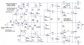
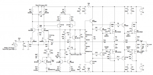
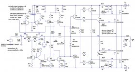
Modification #1: eliminate C17 and C8 100pF caps of the original PCB schematic (shown) and place just C19 15pF cap of aparatusonitus last schematic (shown)
Modification #2: add C1 330pF , R42 100 Ohms, C4 100nF from the aparatusonitus last schematic (shown), to the actual amplifier. Just that.
I have a non heating, no fireworks, almost working amp. I think I should try these. What do you think ? After this test, whether it works or not, the full aparatusonitus modification comes. This needs a new Mouser order and 3 or 4 days delay. Hitachi MOSFETs didn't arrive yet, I paid customs import fees though. But I still need you to help me make the old amp work. My intention is to draw a new PCB with all of the necessary mods, heat sinks, etc. using Exicons.
The good news:
Transistors were placed on the bottom side of the PCB and heat sinks fixed with epoxy on. Q9 and Q12 in thermal contact same as Q10 and Q11. You may try to see this on the pictures. Oscilloscope on output, no speaker connected, Variac for mains, voltmeter across 0.1 Ohms quiescent current monitor, the amplifier turned on, no heating, no oscillation, almost 0mV DC at the output. With input grounded, 0mA quiescent current on output MOSFETs. After this, signal generator, still no speakers, and a light load, obtained 110 Vpp clean sine @ 1kHz before clipping.
The bad news:
Small speakers 8 Ohms connected at the output, small signal input. Unstable, low frequency motor boating noise at, with HF oscillation on top, crossing distortion. Horrible. Still no heating of any kind. Please remember we are talking about the first original schematic here uploaded.
Before devoting myself to aparatusonitus last schematic, I would like to give this original version amp a quick last chance and try just 2 of the modifications proposed. I need your opinion about this. It would take some few minutes and may calm this nervous temperamental Exicon MFs amplifier and put it to work. I think I am near that
Modification #1: eliminate C17 and C8 100pF caps of the original PCB schematic (shown) and place just C19 15pF cap of aparatusonitus last schematic (shown)
Modification #2: add C1 330pF , R42 100 Ohms, C4 100nF from the aparatusonitus last schematic (shown), to the actual amplifier. Just that.
I have a non heating, no fireworks, almost working amp. I think I should try these. What do you think ? After this test, whether it works or not, the full aparatusonitus modification comes. This needs a new Mouser order and 3 or 4 days delay. Hitachi MOSFETs didn't arrive yet, I paid customs import fees though. But I still need you to help me make the old amp work. My intention is to draw a new PCB with all of the necessary mods, heat sinks, etc. using Exicons.
Attachments
Before devoting myself to aparatusonitus last schematic, I would like to give this original version amp a quick last chance and try just 2 of the modifications proposed. I need your opinion about this. It would take some few minutes and may calm this nervous temperamental Exicon MFs amplifier and put it to work. I think I am near thatThe original schematic with modifications #1 & 2 can only work by pure luck...the thing is much more complex than it seems at first glance and includes parameters such as open loop gain, close loop gain, loop gain, etc., etc...
I know, dear aparatusonitus, of course. I will test my luck anyway. Whether it works or not, I will make the next step which is designing a new, fresh PCB for your last schematic. You have done an effort, calculations and wise advising. I could retrieve some by sharing this new version.
Anyway, remember the original sense of this thread. I need to repair a friend's amplifier. At the moment, I have an original working board with Hitachi-s and a new copied PCB that works bad with Exicon-s. Being the MOSFETs the only difference, there must be a simple way to stabilize this amp.
In the meantime I will place an order for the components of you last schematic. Could you please check if you have some last minute addition? I will do some "glue electronics" as you suggested over a copied PCB. Let's see if everythings works fine and if so, the new board will be designed.
Hitachi-s MOSFETs arrived today from Canada. Please, which is the simpler method to correctly measure and see if some matching is possible ?
Attachments
Could you please check if you have some last minute addition? I will do some "glue electronics" as you suggested over a copied PCB. Let's see if everythings works fine and if so, the new board will be designed.
I'm to tired to suggest anything useful...tomorrow maybe.
Hitachi-s MOSFETs arrived today from Canada. Please, which is the simpler method to correctly measure and see if some matching is possible ?
Read carefully Matching L-Mosfets
 , it is now 3:20 am here, I just finished a CPU design, working late. I'll take a real look tomorrow if you don't mind. Could you send me the .asc file ?
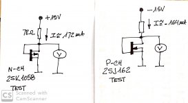
Hello friends ! I am working on the recently arrived Hitachi MOSFETs. This test intends to replace the Exicon MOSFETs now placed in the copied PCB (now with ZETEX transistors), by original 2SK1058/2SJ162 parts. Previous posts explained what happened with this. No heating, but still very unstable if loaded with an 8 Ohms speaker.
Everything indicates that he original MOSFETs must work in an identical PCB.
But before replacing anything, I studied Mr. Nelson Pass document about MOSFET matching, and also the thread that aparatusonitus suggested. The Hitachi MOSFETs need to be paired, same sex units. I 10 pcs of each type, and I need to know if the test is good and if I have some matched pair among them. Attached is the measuring method and here are the results:
10 UNITS N-CHANNEL HITACHI 2SK1058 VGS MEASUREMENT VOLTS:
1.093
1.107
1.109
1.111
1.112
1.115
1.116
1.128
1.131
1.141
10 UNITS P-CHANNEL HITACHI 2SJ162 VGS MEASUREMENT VOLTS:
-1.146
-1.191
-1.249
-1.260
-1.279
-1.286
-1.287
-1.298
-1.318
-1.352
What do you think ? Do I have a couple of paired MOSFETs ? I decided to make 3 second maximum time measurement, previous room temperature leveling, with 15V and about 170 mA. (see picture). Mr. Pass's document IMHO explains the matching of MOSFETs but some details were left out. I assume that the test for verticals needs more VGS than for laterals audio MFs. He uses 3-4 V and I programmed a 15V test not to heat my MOSFETs too much. I really don't know if my test conditions are right. But is a starting point. I could change these conditions and repeat the testing if you think something is wrong.
Attachments
Looks like several good pair-candidates among the K1058's, not quite as close of a grouping among the J162's.
Any of those within 2mV of each other would pair almost as if identical. Even the 3mV difference from 1.128 to 1.131 is only a little higher by percentage.
Of the J162's, the -1.286 and -1.287 would certainly make a fine pair. There are 3 other pairings that are only 7 and 11 mV apart, but two of them include one of the 286/287 devices, which would eliminate that pairing.
Any of the other pairings probably need a Source resistor for the more conductive one. IIRC the Pass paper you linked covers that?
Cheers
Hey Rick ! Nice to hear from you again !
Right !
Good news: I replaced the Exicon MOSFETs in the copied amp board after pairing the Hitachi guys within 1 ~ 2 mV.
It worked perfectly !!! The amp, with the new ZETEX transistors, heat sinks, thermal contact between some transistors, worked without any kind of oscillation. Very stable. Frequency response flat to 300 KHz. I connected a speaker and audio oscillator at the input and could finally hear this amp.
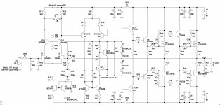
The schematic here is the one that works, except for the Exicons, replaced by matched 2SK1058/2SJ162 and that I pulled C17 and C8 100pF each out from the circuit. I tested reconnecting them and ... it oscillates a little at certain frequencies,
Before choosing the MOSFETs, I ran an extra test but at 40V instead of 15V (please find the text file with the values), same 78 Ohm resistor, to see if the current increase to ~450 mA still left the candidates in the same order, and they did. I thought this last was a more realistic test.
This allows me to finish the damaged amp fixing. My conclusion is that despite this design may have some flaws, it works just fine if Hitachi are used. So Exicon may take some extra work to find stability. In some cases I can see that they are no direct replacements at all just because their have different characteristics. Hitachi are excellent parts but are slower and have greater input capacitance, at least.
I am now ready to start with the experiments previous to the new design, in a few days I believe, after I finish this job for my friend. We will have some fun !
Looks like several good pair-candidates among the K1058's, not quite as close of a grouping among the J162's.
Right !
Good news: I replaced the Exicon MOSFETs in the copied amp board after pairing the Hitachi guys within 1 ~ 2 mV.
It worked perfectly !!! The amp, with the new ZETEX transistors, heat sinks, thermal contact between some transistors, worked without any kind of oscillation. Very stable. Frequency response flat to 300 KHz. I connected a speaker and audio oscillator at the input and could finally hear this amp.
The schematic here is the one that works, except for the Exicons, replaced by matched 2SK1058/2SJ162 and that I pulled C17 and C8 100pF each out from the circuit. I tested reconnecting them and ... it oscillates a little at certain frequencies,
Before choosing the MOSFETs, I ran an extra test but at 40V instead of 15V (please find the text file with the values), same 78 Ohm resistor, to see if the current increase to ~450 mA still left the candidates in the same order, and they did. I thought this last was a more realistic test.
This allows me to finish the damaged amp fixing. My conclusion is that despite this design may have some flaws, it works just fine if Hitachi are used. So Exicon may take some extra work to find stability. In some cases I can see that they are no direct replacements at all just because their have different characteristics. Hitachi are excellent parts but are slower and have greater input capacitance, at least.
I am now ready to start with the experiments previous to the new design, in a few days I believe, after I finish this job for my friend.
We will have some fun !Attachments
Yes Rick !And its making beautiful music! Double yay!!
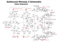
Those capacitors bothered me also, all the time. Specially because I haven't seen them even in the first versions of the supposed original Goldmund M3 schematic from an older thread I followed some time ago. Please see attachment. I bought a couple of PCB's from the OP member and assembled 2 channels with the original parts list. Never worked fine, but the circuit was simpler and almost the same we are discussing here, except for some additions. I'd never liked the ground plane technique, I am more fond of star ground, or single point ground when possible.
I think that the capacitance multiplier for separating power supplies is good. But I wouldn't go back to this subject in this thread, it is probably off topic.
Attachments
Thanks for the schematic -- always great to see another designer's 'take' on the design!
Pretty sure though, that the cap multipliers aren't so much for isolation, as for getting every last possible volt of swing out of the outputs. The 'half-wave, half-voltage doublers' powering the pair of 'super rails' can allow even non-lateral MOSFET's with higher thresholds to pull all the way to the rail.
I'm also kinda drawn to the much simpler driver arrangement -- the extra layer and one-each-per-OP don't appear to give as much benefit as they add extra parasitics. But am also sure that I've been having way too much fun fiddling with it all in LT Spice. May not accomplish much as far as these projects go, but I'm sure toning up my many shortcomings at using the simulator.
Cheers
Last edited:
But I think there must be some influence from the power supply modulated by heavy current demand when operating at relative high power.Pretty sure though, that the cap multipliers aren't so much for isolation, as for getting every last possible volt of swing out of the outputs. The 'half-wave, half-voltage doublers' powering the pair of 'super rails' can allow even non-lateral MOSFET's with higher thresholds to pull all the way to the rail.
Maybe an extra winding from in the power transformer could supply some extra volts considering some voltage drop and a modern integrated voltage regulator could be used for isolation ... I have designed an +/- 80V regulator based upon LM317/LM337 with more than 120 dB rejection.
Yes, there would likely be influence, but maybe the 1st two stages would show good PSRR, since they are all differential up to the current mirror. (But probably I should spend some more time and effort with LT Spice before I shoot my mouth off. Of course, there's always the chance that I'm really just playing with it! )
And the input stage current is set by the CCS, and its PSRR is good (though surely less than 120 dB!). Oh, and, pretty sure T5 in the new schematic is drawn upside down.
-Rick
)And the input stage current is set by the CCS, and its PSRR is good (though surely less than 120 dB!). Oh, and, pretty sure T5 in the new schematic is drawn upside down.
-Rick
Last edited:
- Home
- Amplifiers
- Solid State
- Fixing and troubleshooting this MOSFET amplifier