Hi all.
Apologies if this has been discussed before, could not find anything on it.
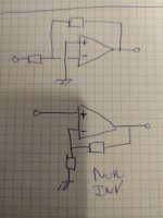
I'm trying to understand why more or less all power amplifiers today are of the non inverting type. I am talking about how the feedback is applied.
Please have a look at the attached image.
I'm not an engineer, and some of my assumptions might be plain wrong. I would however very much like to be enlightened on this subject,
and any assumptions where I am incorrect.
I remember I really enjoyed listening to the Mission 777 back in the day, which was of the inverting type. Unfortunately it wasn't mine.
The schematic can easily be found online. Can't currently remember any others inverting amplifiers… ( Anyone ? )
Non inverting amps...
I can imagine a few reasons why non inverting amplifiers are preferred. I guess they generally have higher input impedance, being easier to drive,
and off cause have correct phase. ( Other reasons? )
That being said, semiconductors are not perfect nor linear. Imagine a typical amplifier with a npn differential input stage.
None of these two transistors are actually inside the feedback loop, are they?
I assume it works because the two transistors are of the same type, hence cancelling out any non linearities.
I guess that's the very same reason why we always try to match them.
Moving to the inverting amplifiers…
If the feedback for an inverting amplifier is applied as shown, I assume that all semiconductors are enclosed by it, theoretically making it more linear.
But why is this configuration rarely seen?
Is it because of nonlinear output impedance of preamps, drive requirements, or maybe cable issues?
I hope for some good comments/explanations, or maybe even a good discussion on this subject")
Thanks to all of you who share your knowledge and/or designs.
Jørgen
Apologies if this has been discussed before, could not find anything on it.
I'm trying to understand why more or less all power amplifiers today are of the non inverting type. I am talking about how the feedback is applied.
Please have a look at the attached image.
I'm not an engineer, and some of my assumptions might be plain wrong. I would however very much like to be enlightened on this subject,
and any assumptions where I am incorrect.
I remember I really enjoyed listening to the Mission 777 back in the day, which was of the inverting type. Unfortunately it wasn't mine.
The schematic can easily be found online. Can't currently remember any others inverting amplifiers… ( Anyone ? )
Non inverting amps...
I can imagine a few reasons why non inverting amplifiers are preferred. I guess they generally have higher input impedance, being easier to drive,
and off cause have correct phase. ( Other reasons? )
That being said, semiconductors are not perfect nor linear. Imagine a typical amplifier with a npn differential input stage.
None of these two transistors are actually inside the feedback loop, are they?
I assume it works because the two transistors are of the same type, hence cancelling out any non linearities.
I guess that's the very same reason why we always try to match them.
Moving to the inverting amplifiers…
If the feedback for an inverting amplifier is applied as shown, I assume that all semiconductors are enclosed by it, theoretically making it more linear.
But why is this configuration rarely seen?
Is it because of nonlinear output impedance of preamps, drive requirements, or maybe cable issues?
I hope for some good comments/explanations, or maybe even a good discussion on this subject
Thanks to all of you who share your knowledge and/or designs.
Jørgen
Attachments
It is true that inverting operation eliminates several distortion sources. See Samuel Groner's opamp measurements.
That said, speaker power amps usually run at high enough gain (>20 dB) for common mode distortion not to be the most pressing problem, and likewise that relatively high gain would also mean relatively low input impedance if you want to keep noise levels low, requiring the preamp to be up to headphone driving duties.
Now try making an amp that preserves absolute phase (more of a matter of convention, but there you go) while providing a standard level of input impedance (e.g. 10k) and largely preserving the noise level of the noninverting config. You can't do it with just inverting stages.
It gets even more hairy by the time you attempt to make an integrated amp with all 42-46 dB at once and a volume control upfront. Though maybe that's still somewhat doable if you include an inverting stage ahead of the volume control and a low-noise unity gain buffer behind it (driving a few hundred ohms at a few hundred mV isn't so bad). Still, that buffer would have to be substantially less noisy than the actual power amp circuitry.
By the time you need additional stages besides the actual power amp, chances are you'll be looking at opamps with their own set of supplies, which increases complexity and may mean that you need either resistor droppers (inefficient), a custom transformer with extra secondaries or a second lower-voltage power transformer.
It's certainly feasible and worth considering if you need some extra circuitry anyway, e.g. for a balanced input (pro amps tend to have an input trim as well).
Inverting operation is a fairly common sight on certain kinds of e.g. headphone driver ICs, which are expected to operate at low to unity gain. Guess it's because their inputs tend to be run at decent current levels and would exhibit a fair amount of input impedance distortion if nothing else.
Last edited:
Well explained by sgrossklaas above.
An inverting amplifier is actually a transimpedance amplifier, whereas the noninv is (from the outside) a voltage amplifier. But the noninv's contain inside several steps: from voltage to current (like OTA's), from current to voltage (like inv amps/ stages) and a voltage follower (= current amplifier). So the inv omits the first stage of the noninv (also inverting). Because the input of the inv is a current input with an impedance near (virtual ground) zero ohms, one had to add an extra stage to fit this. Also explained above.
The endresult is the same.
Thank you sgrossklass and MarsBravo.
Good explanations
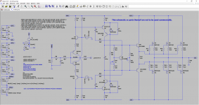
The question actually came to mind because I wanted to play with a new type of input stage. At least it's new for me, haven't seen it before.
When looking at how to implement feedback for this, it seemed to be the obvious choice to make it inverting.
According to ltspice, it's stable, has good phase and gain margin, and it does nice square waves, even with capacitive load.
The distortion isn't as low as I would like, but it's not bad either. Sim it in ltspice and decide for yourself
There is still some work to be done for dc biasing/servo...
Is it worth pursuing? My preamp will easily drive it.
Good explanations
The question actually came to mind because I wanted to play with a new type of input stage. At least it's new for me, haven't seen it before.
When looking at how to implement feedback for this, it seemed to be the obvious choice to make it inverting.
According to ltspice, it's stable, has good phase and gain margin, and it does nice square waves, even with capacitive load.
The distortion isn't as low as I would like, but it's not bad either. Sim it in ltspice and decide for yourself
There is still some work to be done for dc biasing/servo...
Is it worth pursuing? My preamp will easily drive it.
Attachments
The standard input impedance for an amp is 47k or thereabouts (an anachronism really, but there it is), and having a 47k series resistor is just too noisy. Having lower series resistors can cure that, but assumes low impedance source, and can create more input current distortion if the source isn't designed to drive a low impedance.
Also having the black speaker terminal hot and the red one cold may cause confusion and disaster to people who assume the black ones are ground.
But there can be an advantage to inverting topology due to the lack of common-mode signal at the input stage - CMRR is no longer an issue.
Also having the black speaker terminal hot and the red one cold may cause confusion and disaster to people who assume the black ones are ground.
But there can be an advantage to inverting topology due to the lack of common-mode signal at the input stage - CMRR is no longer an issue.
A problem with inverting amplifying circuits is that they have to be stable when the input resistor is not connected to a low impedance voltage source. Some power Ics died in these circumstancces.
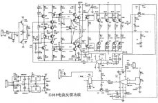
I highly recommend this one, low cost, few components, very high performances : MJR7-Mk5 Mosfet Power Amplifier
The input can be connected to a standard 10 kOhm pot.
I highly recommend this one, low cost, few components, very high performances : MJR7-Mk5 Mosfet Power Amplifier
The input can be connected to a standard 10 kOhm pot.
10k is allowable for most preamps, but most cannot drive lower values indeed.The standard input impedance for an amp is 47k or thereabouts...
Hence the need to lower the input impedance as much as possible (it's a current input!); a shorting would be best......a 47k series resistor is just too noisy...
In your circuit the input impedance is some 5 kohm ( (R8+R12)//R43; presumed a perfect current node 'IN_NFB')
True indeed, so check current capabilities of the pre.Having lower series resistors can cure that, but assumes low impedance source, and can create more input current distortion if the source isn't designed to drive a low impedance.
In the USA (Canada?) it is custom to connect the chassis ground to the protective/safety ground ('earth'), but is rarely seen outside NA.Also having the black speaker terminal hot and the red one cold may cause confusion and disaster to people who assume the black ones are ground.
Currently that's why I favouring this topology now. But as said, input impedance, drive capabilities of the former stage / amp and awareness of outputpolarity has to be addressed carefully.But there can be an advantage to inverting topology due to the lack of common-mode signal at the input stage - CMRR is no longer an issue.
The two transistors making up the LTP input stage are within the loop for differential-mode signals and outside the loop for common-mode signals. Unfortunately the signals applied to them are an even mixture of the two types. Fortunately their common-mode gain is usually small, but sometimes common-mode distortion can catch people out. No amount of feedback can remove CM distortion, because it occurs outside the loop.Onemangang said:That being said, semiconductors are not perfect nor linear. Imagine a typical amplifier with a npn differential input stage.
None of these two transistors are actually inside the feedback loop, are they?
I assume it works because the two transistors are of the same type, hence cancelling out any non linearities.
I guess that's the very same reason why we always try to match them.
Thank you. I was not aware of this. Still learningThe two transistors making up the LTP input stage are within the loop for differential-mode signals and outside the loop for common-mode signals. Unfortunately the signals applied to them are an even mixture of the two types. Fortunately their common-mode gain is usually small, but sometimes common-mode distortion can catch people out. No amount of feedback can remove CM distortion, because it occurs outside the loop.
Thank you. Would you happen to have some links for designs, or names of known amps that use this topology?Currently that's why I favouring this topology now. But as said, input impedance, drive capabilities of the former stage / amp and awareness of outputpolarity has to be addressed carefully.
10k is allowable for most preamps, but most cannot drive lower values indeed.
My "most" you probably mean most valve preamps, as plenty of SS preamps have no issues driving 600ohms or lower. A lot of commercial power amps have an input impedance below 5k and some have optional 50ohm inputs.
It is also possible to solve issues with excessively low input impedance within the power amp itself. Krell and JR use simple (too simple?) buffers at the inputs.
Attachments
Or use a buffer from JLH or some of the ones I simulated here.
JLH Buffer - Homage to John Linsley Hood
JLH Buffer - Homage to John Linsley Hood
Not my circuit, the OP's.10k is allowable for most preamps, but most cannot drive lower values indeed.
Hence the need to lower the input impedance as much as possible (it's a current input!); a shorting would be best...
In your circuit the input impedance is some 5 kohm ( (R8+R12)//R43; presumed a perfect current node 'IN_NFB')
A metal case must be earthed in the UK for any mains appliance. Neither speaker terminal has to be connected to the case though, for instance it wouldn't be in any bridged amp.True indeed, so check current capabilities of the pre.
In the USA (Canada?) it is custom to connect the chassis ground to the protective/safety ground ('earth'), but is rarely seen outside NA.
Can always add an inverting pre-input opamp stage I suppose. If its bypassable you allow for bridge-connecting two of the things.Currently that's why I favouring this topology now. But as said, input impedance, drive capabilities of the former stage / amp and awareness of outputpolarity has to be addressed carefully.
At least for power amps based on the LM3886 chip (~35 - 50W), Bob Cordell advocates operating them in inverting mode. This eliminates input common mode distortion; the common mode input signal in the inverting mode circuit is zero. Here's a page from Bob's website
https://www.cordellaudio.com/poweramp/supergainclone.shtml
https://www.cordellaudio.com/poweramp/supergainclone.shtml
Would you happen to have some links for designs, or names of known amps that use this topology?
Hardly, but I'm busy trying to get an bridged Hiraga in inverting (*) mode to reality. But I'm shure there are.
(*) Not simply two amps in bridge, but a 'intertwined' single with balanced output. That is new.
By "most" you probably mean most valve preamps...
Regarding valve amps, I'm not worried at all if they can drive low impedances, on line or loudspeaker level. They might bent a bit, but are and sound great.
I once put a Philips 2x2W/5ohm ECC83-EL95 on my 50+W ESL's, and it was magnificent! The amp had to retire so now I'm building true triode characteristic semiconducter imposters to fit in the noval feet. Difficult but doable in the end.
Speaking in general, not specific.Not my circuit, the OP's.
You're right. The UK is strict in these matters. I've a lot of 'plugin' switches in the wallplugs to switch off various devices as common in the UK. Save and economical. That would be a good idea to implement into the continental laws!A metal case must be earthed in the UK for any mains appliance. Neither speaker terminal has to be connected to the case though, for instance it wouldn't be in any bridged amp.
Noted ('bypassable'). But such a stage would be comparable with the first transconductance stage (*) used in the noninv amplifiers. Then better incorporate it. Yet, good point of discussion to fork out of this topic.Can always add an inverting pre-input opamp stage I suppose. If its bypassable you allow for bridge-connecting two of the things.
(*) reference to Bruno Putzeys document (The F-word) recently elsewhere refered to on this platform, but lost the link.
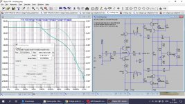
I tried to introduce TPC and here is the result:
Output power 50W and simulated THD
Original MC 1kHz 0.00059%, 8kHz 0.0045%, 10kHz 0.0056%
TPC 1kHz 0.00036%, 8kHz 0.0029%, 10kHz 0.0040%
attached TPC Loop Gain.
I did not change input impedance of the amp, but it needs in this case input buffer or else the source output impedance will influence the amp gain to much. My suggestion is to lower FB resistors.
Attachments
- Status
- This old topic is closed. If you want to reopen this topic, contact a moderator using the "Report Post" button.
- Home
- Amplifiers
- Solid State
- Pros and Cons of inverting vs non inverting poweramp feedback implementation